Chapter 3: GIC Partitioning
-
This chapter describes the GIC logical partitioning. It contains the following sections: • The GIC logical components .
-
Interrupt bypass support .
3.1 The GIC logical components
The GICv3 architecture consists of a set of logical components:
-
A Distributor .
-
A Redistributor for each PE that is supported.
-
A CPU interface for each PE that is supported.
-
Interrupt Translation Service components (ITS), to support the optional translation of events into LPIs.
The Distributor, Redistributor and ITS are collectively known as an IRI.
Figure 3-1 shows the IRI.
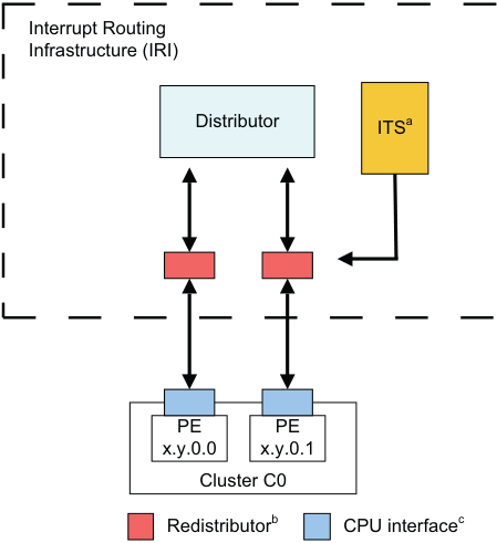
Image text
Interrupt Routing
Infrastructure (IRI)
Distributor ITS [a]
PE PE
x.y.0.0 x.y.0.1
Cluster C0
Redistributor [b] CPU interface [c]
b. There is one Redistributor per PE. c. There is one CPU interface per PE.
Figure 3-1 Interrupt Routing Infrastructure The CPU interface handles physical interrupts at all implemented Exception levels:
-
Interrupts that are translated into LPIs are optionally routed via the ITS to the Redistributor and the CPU interface.
-
PPIs are routed directly from the source to the local Redistributor.
-
SPIs are routed from the source through the Distributor to the target Redistributor and the associated CPU interface.
-
SGIs are generated by software through the CPU interface and Redistributor. They are then routed through the Distributor to one or more target Redistributors and the associated CPU interfaces.
In GICv3, the ITS is an optional component and translates events into physical LPIs. The architecture also supports direct LPIs that do not require the use of an ITS. Where LPIs are supported, it is IMPLEMENTATION DEFINED whether either:
-
Direct LPIs are supported by accessing the registers in the Redistributors.
-
LPI support is provided by the ITS.
An implementation must only support one of these methods.
In GICv4, the inclusion of at least one ITS is mandatory to provide support for the direct injection of virtual LPIs. Figure 3-2 shows the GIC partitioning in an implementation that includes an ITS.
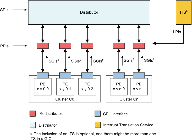
Image text
SPIs
Distributor ITS [a]
LPIs
PPIs
SGIs [b] SGIs [b] SGIs [b] SGIs [b] SGIs [b]
PE PE PE PE PE
x.y.0.0 x.y.0.1 x.y.0.2 x.y.n.0 x.y.n.1
Cluster C0 Cluster Cn
Redistributor CPU interface
Distributor Interrupt Translation Service
a. The inclusion of an ITS is optional, and there might be more than one
ITS in a GIC.
Figure 3-2 GIC logical partitioning with an ITS
The mechanism for communication between the ITS and the Redistributors is IMPLEMENTATION DEFINED.
The mechanism for communication between the CPU interfaces and the Redistributors is also IMPLEMENTATION DEFINED.
Note Arm recommends that an implementation uses the GIC Stream Protocol for communication between the CPU interfaces and the Redistributors, see Appendix A GIC Stream Protocol interface .
Figure 3-3 shows the GIC partitioning in an implementation that does not include an ITS and that supports direct LPIs. 3.1 The GIC logical components
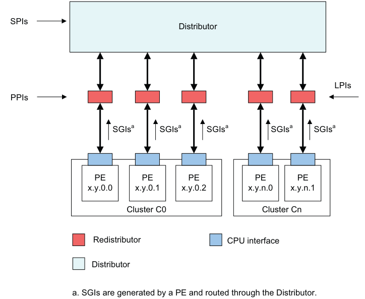
Image text
SPIs
Distributor
LPIs
PPIs
SGIs [a] SGIs [a] SGIs [a] SGIs [a] SGIs [a]
PE PE PE PE PE
x.y.0.0 x.y.0.1 x.y.0.2 x.y.n.0 x.y.n.1
Cluster C0 Cluster Cn
Redistributor CPU interface
Distributor
a. SGIs are generated by a PE and routed through the Distributor.
The following list describes the components that are depicted in Figure 3-2 in more detail:
Distributor
The Distributor performs interrupt prioritization and distribution of SPIs and SGIs to the Redistributors and CPU interfaces that are connected to the PEs in the system. GICD_CTLR provides global settings for:
-
Enabling affinity routing.
-
Disabling security.
-
Enabling Secure and Non-secure Group 1 interrupts.
-
Enabling Group 0 interrupts.
For SPIs, the Distributor provides a programming interface for:
-
Enabling or disabling SPIs.
-
Setting the priority level of each SPI.
-
Routing information for each SPI.
-
Setting each SPI to be level-sensitive or edge-triggered.
-
Generating message-based SPIs.
-
Assigning each SPI to an interrupt group.
-
Controlling the pending and active state of SPIs.
The Distributor registers are identified by the GICD_ prefix.
See Chapter 2 Distribution and Routing of Interrupts for more information.
Note When handling physical interrupts during legacy operation, the Distributor controls the configuration information for PPIs and SGIs. See Chapter 14 Legacy Operation and Asymmetric Configurations .
Interrupt translation service, ITS
The ITS is an OPTIONAL hardware mechanism in the GICv3 architecture that routes LPIs to the appropriate Redistributor. Software uses a command queue to configure an ITS. Table structures in memory that are associated with an ITS translate an EventID associated with a device into a pending INTID for a PE.
The ITS is not optional in GICv4, and all GICv4 implementations must include at least one ITS.
See The Interrupt Translation Service for more information.
Redistributor A Redistributor is the part of the IRI that is connected to the CPU interface of the PE. The Redistributor holds the control, prioritization, and pending information for all physical LPIs using data structures that are held in memory. Two registers in the Redistributor point to these data structures:
-
GICR_PROPBASER.
-
GICR_PENDBASER.
In GICv4, the Redistributor also includes registers to handle virtual LPIs that are forwarded by an ITS to a Redistributor and directly to a VM, without involving the hypervisor. This is referred to as a direct injection of virtual interrupts into a VM.
In GICv4, the Redistributors collectively host the control, prioritization, and pending information for all virtual LPIs using data structures that are held in memory. Two registers in the Redistributor point to these data structures:
-
GICR_VPROPBASER.
-
GICR_VPENDBASER.
In an implementation that supports LPIs but does not include an ITS, the GICR_* registers contain a simple memory-mapped interface to signal and control physical LPIs.
Redistributors provide a programming interface for:
-
Identifying, controlling, and configuring supported features to enable interrupts and interrupt routing of the implementation.
-
Enabling or disabling SGIs and PPIs.
-
Setting the priority level of SGIs and PPIs.
-
Setting each PPI to be level-sensitive or edge-triggered.
-
Assigning each SGI and PPI to an interrupt group.
-
Controlling the pending state of SGIs and PPIs.
-
Controlling the active state of SGIs and PPIs.
-
Power management support for the connected PE.
-
Where LPIs are supported, base address control for the data structures in memory that support the associated interrupt properties and their pending status.
-
Where GICv4 is supported, base address control for the data structures in memory that support the associated virtual interrupt properties and their pending status.
The Redistributor registers are identified by the GICR_ prefix.
See Affinity routing and The Distributor and Redistributors for more information about the Redistributor.
CPU interface
The GIC architecture supports a CPU interface that provides a register interface to a PE in the system. Each CPU interface provides a programming interface for:
-
General control and configuration to enable interrupt handling in accordance with the Security state and legacy support requirements of the implementation.
-
Acknowledging an interrupt.
-
Performing a priority drop.
-
Deactivation of an interrupt.
-
Setting an interrupt priority mask for the PE.
-
Defining the preemption policy for the PE.
-
Determining the highest priority pending interrupt for the PE.
The CPU interface has several components:
-
A component that allows a supervisory level of software to control the handling of physical interrupts. The registers that are associated with this are identified by the ICC_ prefix.
-
A component that allows a supervisory level of software to control the handling of virtual interrupts. The registers that are associated with this are identified by the ICV_ prefix.
-
A component that allows a hypervisor to control the set of pending interrupts. The registers that are associated with this are identified by the ICH_ prefix.
Note The System registers in the CPU interface are associated with software that is handling interrupts in the physical domain, or with execution at Non-secure EL1 as part of a VM. The configuration of HCR_EL2 determines whether the accesses are to the physical resources or the virtual resources.
The System registers accessible at EL2 that are used for controlling the list of active, pending, and active and pending, virtual interrupts for a PE are identified by the ICH_ prefix.
For more information on handling physical interrupts, see Chapter 4 Physical Interrupt Handling and Prioritization .
For more information on handling virtual interrupts, see Chapter 6 Virtual Interrupt Handling and Prioritization .
3.2 Interrupt bypass support
A CPU interface optionally includes interrupt signal bypass, so that, when the signaling of an interrupt by the interface is disabled, a legacy interrupt signal is passed to the interrupt request input on the PE, bypassing the GIC functionality.
It is IMPLEMENTATION DEFINED whether bypass is supported.
The controls to determine whether GICv3 FIQ and IRQ outputs or the bypass signals are used differ depending on whether System register access is enabled.
When System register access is enabled, bypass disable is controlled at the highest implemented Exception level using two bits in ICC_SRE_EL1, ICC_SRE_EL2, or ICC_SRE_EL3, as appropriate:
-
For FIQ bypass, this is the DFB bit.
-
For IRQ bypass, this is the DIB bit.
This bypass mechanism is used when System register access is enabled. For information about bypass support during legacy operation, see Legacy operation and bypass support .
The interrupt groups that are supported by the GIC are allocated to FIQs and IRQs, as described in Interrupt grouping . Interrupt groups must be disabled at the CPU interface when bypass is enabled, otherwise the behavior of the GICv3 implementation is UNPREDICTABLE. This means that:
-
ICC_IGRPEN0_EL1.Enable must have the value 0 when ICC_SRE_ELx.DFB == 0.
-
ICC_IGRPEN1_EL1.Enable must have the value 0 when ICC_SRE_ELx.DIB == 0.
For more information about enabling interrupts, see Enabling the distribution of interrupts .
For information about the behavior when System register access is not enabled, see Chapter 14 Legacy Operation and Asymmetric Configurations .
For FIQs, the following pseudocode determines the source for interrupt signaling to a PE.
if ICC_SRE_EL3.SRE == 1 then
    if ICC_SRE_EL3.DFB == 0 then
        if ICC_SRE_EL1.SRE Secure == 1 then
            BypassFIQsource
        else
            use legacy bypass support
    else
        use GICv3 FIQ output
else
    use legacy bypass support
For IRQs, the following pseudocode determines the source for interrupt signaling to a PE.
if ICC_SRE_EL3.SRE == 1 then
    if ICC_SRE_EL3.DIB == 0 then
        if ICC_SRE_EL1.SRE Secure == 1 then
            BypassIRQsource
        else
            use legacy bypass support
    else
        use GICv3 IRQ output
else
    use legacy bypass support