Chapter 5: Locality-specific Peripheral Interrupts and the ITS
This chapter describes Locality-specific Peripheral Interrupts (LPIs) and the Interrupt Translation Service (ITS). It contains the following sections:
-
LPIs.
-
The Interrupt Translation Service.
-
ITS commands.
-
Common ITS pseudocode functions.
-
ITS command error encodings.
-
ITS power management.
5.1 LPIs
Locality-specific Peripheral Interrupts (LPIs) are edge-triggered message-based interrupts that can use an Interrupt Translation Service (ITS), if it is implemented, to route an interrupt to a specific Redistributor and connected PE. GICv3 provides two types of support for LPIs. LPIs can be supported either:
-
Using the ITS to translate an EventID from a device into an LPI INTID. For more information about EventIDs, see The Interrupt Translation Service.
-
By forwarding an LPI INTID directly to the Redistributors, using GICR_SETLPIR.
An implementation must support only one of these methods.
Note
The following registers are mandatory in an implementation that supports LPIs but does not include an ITS:
-
GICR_INVLPIR.
-
GICR_INVALLR.
-
GICR_SYNCR.
Support for these registers is IMPLEMENTATION DEFINED in implementations that do include an ITS.
These registers control physical LPIs in a system that does not include an ITS:
-
GICR_SETLPIR.
-
GICR_CLRLPIR.
In an implementation that includes LPIs, at least 8192 LPIs are supported. For this reason, the configuration of each interrupt, and the pending information for each interrupt, is held in tables in memory, rather than in registers, and the tables are pointed to by registers held in the Redistributors.
Note
-
Arm expects that an implementation will cache parts of the tables in the Redistributors to reduce latency and memory traffic. The form of these caches is IMPLEMENTATION DEFINED.
-
The addresses for the LPI tables are in the Non-secure physical address space.
Figure 5-1 shows the generation of LPIs in an implementation that includes at least one ITS.
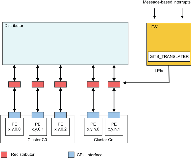
Image text
Message-based interrupts
Distributor ITS [a]
GITS_TRANSLATER
LPIs
PE PE PE PE PE
x.y.0.0 x.y.0.1 x.y.0.2 x.y.n.0 x.y.n.1
Cluster C0 Cluster Cn
Redistributor CPU interface
Figure 5-1 Triggering LPIs in an implementation with an ITS
Note In Figure 5-1, the ITS channel to the Redistributors is IMPLEMENTATION DEFINED.
Figure 5-2 shows the generation of LPIs in an implementation without an ITS. 5.1 LPIs
Message-based interrupts
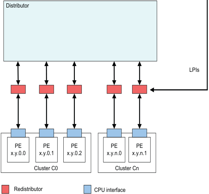
Image text
Distributor
LPIs
PE PE PE PE PE
x.y.0.0 x.y.0.1 x.y.0.2 x.y.n.0 x.y.n.1
Cluster C0 Cluster Cn
Redistributor CPU interface
-
LPIs are only supported when affinity routing is enabled for Non-secure state.
-
LPIs are always Non-secure Group 1 interrupts.
When GICD_CTLR.DS == 1:
-
LPIs are only supported when affinity routing is enabled.
-
LPIs are always Group 1 interrupts.
There is a single global physical LPI space so that LPIs can be moved between all Redistributors. Software programs the size of the single global physical LPI space using GICR_PROPBASER.IDbits.
Note The size of the physical LPI space is limited to the maximum size that an implementation supports, which is defined in GICD_TYPER.IDbits.
For a given Redistributor, LPI configuration and state are maintained in two tables in memory, described in the following sections:
-
LPI Configuration tables.
-
LPI Pending tables. If a Redistributor supports physical LPIs, it has:
-
LPI priority and enable bits programmed in the LPI Configuration table. The address of the LPI Configuration table is defined by GICR_PROPBASER. If GICR_PROPBASER is updated when GICR_CTLR.EnableLPIs == 1, the effects are UNPREDICTABLE. See LPI Configuration tables for more information.
-
Memory-backed storage for LPI pending bits in an LPI Pending table. This table is specific to a particular Redistributor. The address of the LPI Pending table is defined by GICR_PENDBASER. If GICR_PENDBASER is updated when GICR_CTLR.EnableLPIs == 1, the effects are UNPREDICTABLE.
GICR_PROPBASER.IDBits sets the size of the ID space, and thereby the number of entries in the LPI Configuration table and the corresponding LPI Pending table.
Physical LPIs are enabled by a write to GICR_CTLR.EnableLPIs.
Note
When LPIs are disabled at the Redistributor interface, that is when GICR_CTLR.EnableLPIs == 0, LPIs cannot become pending. An attempt to make an LPI pending in this situation has no effect, and the LPI is lost. This differs from disabling SGIs, PPIs, and SPIs, which prevents only the signaling of the interrupt to the CPU interface.
GICv4 introduces equivalent tables for handling virtual LPIs with addresses referenced in GICR_VPROPBASER and GICR_VPENDBASER.
In GICv4, virtual LPIs are enabled by a write to GICR_VPENDBASER.Valid.
5.1.1 LPI Configuration tables
LPI configuration is global. Whether a GIC supports Redistributors that point at different copies of the LPI Configuration table is IMPLEMENTATION DEFINED.
It is IMPLEMENTATION DEFINED whether GICR_PROPBASER can be set to different values on different Redistributors. GICR_TYPER.CommonLPIAff indicates which Redistributors must have GICR_PROPBASER set to the same value whenever GICR_CTLR.EnableLPIs == 1.
An implementation can treat all copies of GICR_PROPBASER that are required to have the same value as accessing common state.
Setting different values in different copies of GICR_PROPBASER on Redistributors that are required to use a common LPI Configuration table when GICR_CTLR.EnableLPIs == 1 leads to UNPREDICTABLE behavior.
If GICR_PROPBASER is programmed to different values on different Redistributors, it is IMPLEMENTATION DEFINED which copy or copies of GICR_PROPBASER are used when the GIC reads the LPI Configuration tables. However, the copy or copies that are used will correspond to a Redistributor on which GICR_CTLR.EnableLPIs == 1.
To avoid unpredictable behavior, software must ensure that all copies of the LPI Configuration tables are identical, and all changes are globally observable, whenever:
-
GICR_CTLR.EnableLPIs is written from 0 to 1 on any Redistributor.
-
GICR_INVLPIR and GICR_INVALLR are written on any Redistributor with GICR_CTLR.EnableLPIs == 1, if direct LPIs are supported.
-
The INV and INVALL command is executed by an ITS, in an implementation that includes at least one ITS.
An LPI Configuration table in memory stores entries containing configuration information for each LPI, where:
-
GICR_PROPBASER specifies a 4KB aligned physical address. This is the LPI Configuration table base address.
-
For any LPI N, the location of the table entry is defined by (base address + (N – 8192)).
To change the configuration of an interrupt, software writes to the LPI Configuration tables and then issues the INV or INVALL command. In implementations that do not include an ITS, software writes to GICR_INVALLR or GICR_INVLPIR. 5.1 LPIs
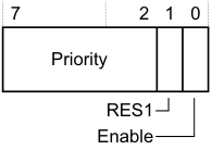
The LPI Configuration table contains an 8-bit entry for each LPI. Figure 5-3 shows the LPI Configuration table entry format.
7 2 1 0
Priority
RES1
Enable
Figure 5-3 LPI Configuration table entry
Table 5-1 shows the LPI Configuration table entry bit assignments.
Table 5-1 LPI Configuration table entry bit assignments
| Bits Name | Function |
|---|---|
| [7:2] Priority | The priority of the LPI. These are the most significant bits of the LPI priority. Bits[1:0] of the priority are 0. WhenGICD_CTLR.DS == 0, this value is shifted in accordance with the security and priority rules specified in_Software accesses of interrupt priority_on page 4-75. This means that LPI priorities are always in the lower half of the priority range. The priority value range is 128-254. IfGICD_CTLR.DS == 1, the value in this field is not shifted. In GICv4, the Virtual LPI Configuration tables behave as ifGICD_CTLR.DS == 1 and therefore the priority is not shifted. Note An implementation might support fewer than 8 bits of priority. Unimplemented bits will be treated asRES0. |
| See_Interrupt prioritization_on page 4-68for more information about interrupt priorities. | ||
|---|---|---|
| [1] | - | RES1. |
| [0] | Enable | LPI enable. This bit controls whether the LPI is enabled: 0 The LPI is not enabled. 1 The LPI is enabled. |
Caching
A Redistributor can cache the information from the LPI Configuration tables pointed to by GICR_PROPBASER, when GICR_CTLR.EnableLPI == 1, subject to all of the following rules:
-
Whether or not one or more caches are present is IMPLEMENTATION DEFINED. Where at least one cache is present, the structure and size is IMPLEMENTATION DEFINED.
-
An LPI Configuration table entry might be allocated into the cache at any time.
-
A cached LPI Configuration table entry is not guaranteed to remain in the cache.
-
A cached LPI Configuration table entry is not guaranteed to remain incoherent with memory.
-
A change to the LPI configuration is not guaranteed to be visible until an appropriate invalidation operation has completed:
- If one or more ITS is implemented, invalidation is performed using the INV or INVALL command. A SYNC command completes the INV and INVALL commands.
-
If no ITS is implemented, invalidation is performed by writing to GICR_INVALLR or GICR_INVLPIR.
If there is no Redistributor with GICR_CTLR.EnableLPIs == 1, the GIC has no cached LPI Configuration table entries.
5.1.2 LPI Pending tables
Software configures the LPI Pending tables, using the implemented range of valid LPI INTIDs, by writing to GICR_PENDBASER. This register provides the base address of the LPI Pending table for physical LPIs.
Each Redistributor maintains entries in a separate LPI Pending table that indicates the pending state of each LPI when GICR_CTLR.EnableLPIs == 1 in the Redistributor:
0 The LPI is not pending. 1 The LPI is pending.
For a given LPI:
-
The corresponding byte in the LPI Pending table is (base address + (N / 8)).
-
The bit position in the byte is (N MOD 8).
An LPI Pending table that contains only zeros, including in the first 1KB, indicates that there are no pending LPIs.
The first 1KB of the LPI Pending table is IMPLEMENTATION DEFINED. However, if the first 1KB of the LPI Pending table and the rest of the table contain only zeros, this must indicate that there are no pending LPIs.
The first 1KB of memory for the LPI Pending tables must contain only zeros on initial allocation, and this must be visible to the Redistributors, or else the effect is unpredictable.
During normal operation, the LPI Pending table is maintained solely by the Redistributor.
Behavior is UNPREDICTABLE if software writes to the LPI Pending tables while GICR_CTLR.EnableLPIs == 1. When GICR_CTLR.EnableLPIs is cleared to 0, behavior is UNPREDICTABLE if the LPI Pending table is written before GICR_CTLR.RWP reads 0.
Redistributors that are required to share a common LPI Configuration table, as indicated by GICR_TYPER.CommonLPIAff, might treat the OuterCache, Shareability, or InnerCache fields of GICR_PENDBASER as accessing common state.
Having the OuterCache, Shareability, or InnerCache fields of GICR_PENDBASER are programmed to different values on different Redistributors with GICR_CTLR.EnableLPIs == 1 in a system is unpredictable.
For physical LPIs, when GICR_CTLR.EnableLPIs is changed to 1, the Redistributor must read the pending status of the physical LPIs from the physical LPI Pending table.
Note
If GICR_PENDBASER.PTZ == 1, software guarantees that the LPI Pending table contains only zeros, including in the first 1KB. In this case hardware might not read any part of the table.
If GICR_CTLR.EnableLPIs is cleared to 0, then when GICR_CTLR.RWP reads as 0 there are no further accesses by the GIC to the LPI Pending table, and any caching of the LPI Pending table is invalidated. There is no guarantee that clearing GICR_CTLR.EnableLPIs causes the LPI Pending table to be updated in memory.
Note
If one or more ITS is implemented, Arm strongly recommends that all LPIs are mapped to another Redistributor before GICR_CTLR.EnableLPIs is cleared to 0.
For virtual LPIs, when GICR_CTLR.EnableLPIs ==1, and GICR_VPENDBASER.Valid is changed to 1, the Redistributor must read the pending status of the virtual LPIs from the virtual LPI Pending table.
Note
-
If GICR_VPENDBASER.IDAI == 0, the software guarantees that the LPI Pending table was written out by the same GIC implementation, meaning that hardware can rely on the first 1KB of the table and might not read the entire table.
-
If GICR_PROPBASER.IDbits is less than 0b1101 when GICR_CTLR.EnableLPIs == 1, the GIC might still access the IMPLEMENTATION DEFINED region of the LPI Pending table.
5.1.3 Virtual LPI Configuration tables and virtual LPI Pending tables
GICv4 uses the same concept of memory tables to hold the configuration and pending information for virtual LPIs. The format of these tables is the same as for physical LPIs.
5.2 The Interrupt Translation Service
The Interrupt Translation Service (ITS) translates an input EventID from a device, identified by its DeviceID, and determines:
-
The corresponding INTID for this input.
-
The target Redistributor and, through this, the target PE for that INTID.
For GICv3, the ITS performs this function for events that are translated into physical LPIs. LPIs can be forwarded to a Redistributor either by an ITS or by a direct write to GICR_SETLPIR. An implementation must support only one of these methods.
For GICv4, the ITS also performs this function for interrupts that are directly injected as virtual LPIs, and for GICV4.1, virtual SGIs.
An ITS has no effect on physical SGIs, SPIs, or PPIs.
The flow of the ITS translation is as follows:
-
The DeviceID selects a Device table entry (DTE) in the Device table that describes which Interrupt translation table (ITT) to use.
-
The EventID selects an Interrupt translation entry (ITE) in the ITT that describes:
-
For physical interrupts:
-
The output physical INTID.
-
The Interrupt collection number , ICID.
-
-
For virtual interrupts, in GICv4:
-
The output virtual INTID.
-
The vPEID.
-
A doorbell to use if the vPE is not scheduled.
-
-
-
For physical interrupts, ICID selects a Collection table entry in the Collection table (CT) that describes the target Redistributor, and therefore the target PE, to which the interrupt is routed.
-
For virtual interrupts, in GICv4, the vPEID selects a vPE table entry that describes the Redistributor that is currently hosting the target vPE to which the interrupt is routed.
The tables used in the translation process are described in more detail in the following sections:
-
The ITS tables .
-
The Device table.
-
The Interrupt translation table.
-
The Collection table.
-
The vPE table.
These tables are created and maintained using the ITS commands described in ITS commands. GICv3 and GICv4 do not support direct access to the tables, and the tables must be configured using the ITS commands.
5.2.1 The ITS tables
Software provisions memory for the ITS private tables when the GIC provides a set of registers that permits the following features to be discovered:
-
The number of private tables that are required.
-
The size of each entry in each table.
-
The type of each table.
Note
All ITS tables are in the Non-secure physical address space.
The state and configuration of the ITS tables is stored in a set of tables in memory. This memory is allocated by software before enabling the ITS.
GITS_BASER
The ITS tables have either a flat structure or a two-level structure. The structure is determined by GITS_BASER
-
0 Flat table. In this case a contiguous block of memory is allocated for the table. The format of the table is IMPLEMENTATION DEFINED.
- Behavior is UNPREDICTABLE if memory that is used for the ITS tables does not contain zeros at the time of the new allocation for use by the ITS.
-
1 Two-level table. In this case each entry in the level 1 table is 64 bits, and has the following format:
-
Bit[63] - Valid:
-
If this bit is cleared to 0, the PhysicalAddress field does not point to the base address of a level 2 table.
-
If this bit is set to 1, the PhysicalAddress field points to the base address of a level 2 table.
-
-
Bits[62:52] - RES 0.
-
Bits[51:N] - PhysicalAddress of the level 2 table. N is the number of bits that are required to specify the page size:
- The size of the level 2 table is determined by GITS_BASER
.Page_Size.
- The size of the level 2 table is determined by GITS_BASER
-
Bits[N-1:0] - RES 0. N is the number of bits that are required to specify the page size.
-
The level 1 table is indexed by the appropriate ID so that level 1 entry = ID/(Page Size / Entry Size).
-
Note This allows software to determine the level 2 table that must be allocated for a given CollectionID, DeviceID, or vPEID.
For level 1 table entries, when Valid == 0:
-
If the Type field specifies a valid table type other than a Collection table, the ITS discards any writes to the level 2 table.
-
If the Type field specifies the Collection table, and ICID is greater than or equal to the number indicated by GITS_TYPER.HCC, the ITS discards any writes to the level 2 table.
The format of the level 2 table is IMPLEMENTATION DEFINED.
Behavior is UNPREDICTABLE if:
-
Memory that is used for the level 2 tables does not contain zeros at the time of the new allocation for use by the ITS.
-
Multiple level 1 table entries with Valid == 1 point to the same level 2 table.
Note As part of restoring the state of the ITS from powerdown events, the registers that describe the table can point to tables that were previously populated by the ITS, and so might contain values other than zeros. The details of power management of the ITS are IMPLEMENTATION DEFINED. See ITS power management.
Figure 5-4 shows how these tables are used in the translation process.
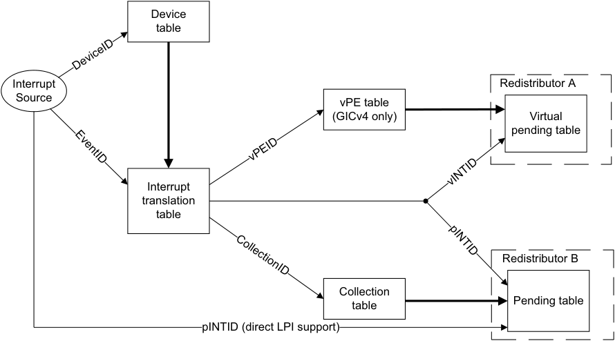
Image text
Device
table
Interrupt Redistributor A
Source
vPE table
(GICv4 only) Virtual
pending table
Interrupt
translation
table
Redistributor B
Collection
table Pending table
pINTID (direct LPI support)
DeviceID
vPEID
CollectionID
vINTID
EventID
pINTID
When GITS_CTLR.Enabled is written from 0 to 1 behavior is UNPREDICTABLE if any of the following conditions are true:
-
GITS_CBASER.Valid == 0.
-
GITS_BASER
.Valid == 0, for any GITS_BASER register where the Type field indicates Device. -
GITS_BASER
.Valid == 0, for any GITS_BASER register where the Type field indicates collection and GITS_TYPER.HCC == 0. -
In GICv4, GITS_BASER
.Valid == 0, for any GITS_BASER register where the Type field indicates a vPE.
Software access to the private ITS tables.
If GITS_BASER
If GITS_BASER
When GITS_CTLR.Enabled == 0 and GITS_CTLR.Quiescent == 1:
- An implementation will not access the tables that are pointed to by any of the GITS_BASER
registers.
When GITS_CTLR.Enabled == 1 or GITS_CTLR.Quiescent == 0:
-
An implementation will not access a table that is pointed to by any GITS_BASER
register for which GITS_BASER .Valid == 0. -
For a table that is pointed to by a GITS_BASER
register for which GITS_BASER .Valid == 1 and GITS_BASER .Indirect == 0, behavior is UNPREDICTABLE if the table is written by software. -
For a table that is pointed to by a GITS_BASER
register for which GITS_BASER .Valid == 1 and GITS_BASER .Indirect == 1: -
Behavior is UNPREDICTABLE if any of the level 2 table entries are written by software.
-
An ITS will not cache any entry in the level 1 table where the valid bit is cleared to 0.
-
-
Behavior is UNPREDICTABLE if any level 1 table entry where the valid bit set to 1 is written by software.
-
A write to a level 1 table entry that changes the valid bit from 0 to 1 must be globally visible before software adds a command to the ITS command queue that relies on that entry. Otherwise it is UNKNOWN if the command will succeed or if it will be ignored.
5.2.2 Interrupt collections
In GICv3, the ITS considers all physical LPIs that it generates to be members of collections . The data that is associated with a collection can be held in the ITS, in external memory, or in both. The ITS supports collections that are held in memory if any of the GITS_BASER
-
When the ITS supports collections that are held in memory, the total number of collections that is supported is determined by the memory allocated by software:
-
If GITS_BASER
.Indirect == 0, the number of collections supported in memory can be calculated using the following formula:
((number of pages * page size) / entry size) The relevant values for this formula are indicated in GITS_BASER
- If GITS_BASER
.Indirect == 1, the number of collections supported in memory can be calculated using the following formula:
(((number of pages in level 1 table * page size) /8) * (page size/entry size)). The relevant values for this formula are indicated in GITS_BASER
Note
Indirect tables allow sparse allocations, so not all ICIDs in the supported range might be usable.
- Where collections are held in both the ITS and external memory, the total number of collections is indicated by GITS_TYPER.CCT.
When GITS_TYPER.HCC!= 0:
-
Collections with identifiers in the range {0… GITS_TYPER.HCC-1} are held in the ITS.
-
Collections with identifiers in the range greater than that indicated in GITS_TYPER.HCC are held in external memory, if this is supported.
When GITS_TYPER.HCC == 0:
- The ITS must support collections in external memory, and all collections are held in external memory.
The maximum number of collections that are supported is limited by the size of the ICID:
-
If GITS_TYPER.CIL == 0, the ICID is 16 bits.
-
If GITS_TYPER.CIL == 1, the ICID is reported by GITS_TYPER.CIDbits.
5.2.3 The Device table
The Device table provides a table of Device table entries (DTEs). Each DTE describes a mapping between a DeviceID and an ITT base address that points to the memory that the ITS can use to store the translations for the EventID. The ITS uses the ITT to store the translations for every EventID for the specified DeviceID. The DeviceID is a unique identifier assigned to each device that can create a range of EventIDs. For example, Arm expects that the 16-bit Requester ID from a PCIe Root Complex is presented to an ITS as a DeviceID.
The DeviceID provides the index value for the table. Table 5-2 shows an example of the number of bits that might be assigned to each DTE.
Table 5-2 DTE entries
| Number of bits | Assignment | Notes |
|---|---|---|
| 1 | Valid | Boolean |
| 40 | ITT Address | Base physical address |
| 5 | ITT Range | Log2 (EventID width supported by the ITT) minus one. |
5.2.4 The Interrupt translation table
An Interrupt translation table (ITT) is specific to each device that can create numbered events. Each entry in an ITT is referred to as an Interrupt translation entries (ITEs).
In GICv3, ITEs are only defined for physical interrupts.
In GICv4, ITEs are defined for physical interrupts and for virtual interrupts, and provide a distinction between:
-
An entry for a physical LPI and the use of an ICT for routing information.
-
An entry for a virtual LPI and the use of a vPE table .
An ITT must be assigned a contiguous physical address space starting at ITT Address. The size is 2^(DTE.ITT Range + 1)* GITS_TYPER.ITT_entry_size.
Behavior is UNPREDICTABLE if the memory does not contain all zeros at the time of new allocation for use by the ITS.
If multiple ITTs overlap in memory, behavior is UNPREDICTABLE.
ITS accesses to an ITT use the same Shareability and Cacheability attributes that are specified for the Device table.
For physical interrupts, each ITE describes the mapping between the input EventID and:
-
The output physical INTID (pINTID) that is sent to the target PE.
-
The ICID that identifies an entry in the Collection table, that determines the target PE for the LPI. For more information about the Collection table, see The Collection table.
For virtual interrupts, each ITE describes the mapping of the EventID as outlined in the preceding list, and:
-
The output virtual INTID (vINTID) that is sent to the target vPE.
-
The virtual PE number (vPEID) that identifies an entry in the vPE table to determine the current host Redistributor. For more information about the vPE table, see The vPE table.
-
A physical LPI that is sent to a physical PE if a virtual interrupt is translated when the target vPE is not currently scheduled on a physical PE.
The EventID provides the index value for the table.
Table 5-3 shows an example of the number of bits that might be stored in an ITE.
Table 5-3 ITE entries
| Number of bits | Assignment | Notes |
|---|---|---|
| 1 | Valid | Boolean |
| 1 | Interrupt_Type | Boolean, indicates whether the interrupt is physical or virtual. |
| Size of the LPI number spacea | Interrupt_Number | pINTID or vINTID depending on the interrupt type. |
| Table 5-3 ITE entries (continued) |
| Number of bits | Assignment | Notes |
|---|---|---|
| Size of the LPI | Interrupt_Number | In GICv4 pINTID is used as a doorbell. In GICv3, and in |
| number spacea | HypervisorID | GICv4 when a doorbell is not required, the programmed value is 1023. |
| 16 | ICID | Interrupt Collection ID, for physical interrupts only. |
| 16 | vPEID | vPE ID, for virtual interrupt only. |
a. For information about the size of the LPI number space, see INTIDs.
5.2.5 The Collection table
The Collection table (CT) provides a table of Collection table entries (CTEs). For physical LPIs only, each CTE describes a mapping between:
-
The ICID generated by the ITT.
-
The address of the target Redistributor in the format defined by GITS_TYPER.PTA.
There is a single CT for each ITS, which can be held in registers or in memory, or in a combination of the two. See GITS_BASER
The TableID provides the index value for the table. It is derived from ICID.
Table 5-4 shows an example of the number of bits that might be assigned to each CT.
Table 5-4 CT entries
| Number of bits | Assignment | Notes |
|---|---|---|
| 1 | Valid | Boolean |
| Size of RDbase identifier | RDbase | The GIC supports two formats for RDbase, seeRDbase |
5.2.6 The vPE table
The vPE table consists of vPE table entries that provide a mapping from the vPEID generated by the ITS to:
-
The target Redistributor, in the format defined by GITS_TYPER.PTA.
-
The base address of the virtual LPI Pending table associated with the target vPE.
An area of memory defined by GITS_BASER
The vPE table describes all the vPEs associated with an ITS. Table 5-5 shows an example of the number of bits that an implementation might store in a vPE table. The 16-bit vPEID provides the index value for the table.
Table 5-5 vPE table entries
| Number of bits | Assignment | Notes |
|---|---|---|
| 1 | Valid | Boolean |
| Size of RDbase identifier | RDbase | The GIC supports two formats forRDbase. |
| Size of | VPT_addr | VPT_addr locates the LPI Pending table when the VM is not |
| address | resident in the Redistributor. It is used as the address in GICR_VPENDBASERwhen the vPE is scheduled in the GICR_* registers associated with RDbase. | |
| 5 | Size | The size of the vINTID range supported (minus one). |
5.2.7 Control and configuration of the ITS
An ITS is controlled and configured using a memory-mapped interface where:
-
The version can be read from GITS_IIDR and from GITS_PIDR2.
-
GITS_TYPER specifies the features that are supported by an ITS.
-
GITS_CTLR controls the operation of an ITS.
-
GITS_TRANSLATER receives EventID information. It is IMPLEMENTATION DEFINED how the DeviceID is supplied. See ITS commands for more details.
-
GITS_BASER
registers provide information about the type, size and access attributes for the architected ITS memory structures. -
GITS_CBASER, GITS_CREADR, and GITS_CWRITER store address information for the ITS command queue interface.
There is an enable bit for each ITS, GITS_CTLR.Enabled.
5.2.8 The ITS command interface
Figure 5-5 shows how the ITS provides the base address and the size that are used by the ITS command queue.
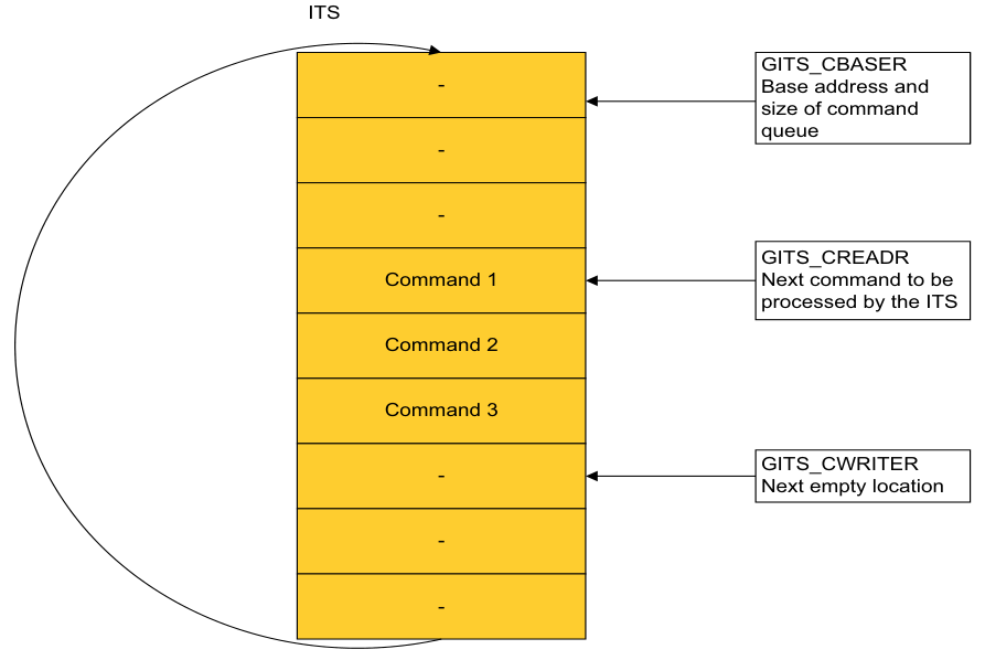
Image text
ITS
GITS_CBASER
- Base address and
size of command
queue
-
-
GITS_CREADR
Command 1 Next command to be
processed by the ITS
Command 2
Command 3
- GITS_CWRITERNext empty location
-
-
GITS_CBASER, GITS_CREADR, and GITS_CWRITER define the ITS command queue.
-
GITS_CBASER uses the following fields:
-
Valid. This field indicates the allocation of memory for the ITS command queue.
-
Cacheability. This field indicates the cacheability attributes of accesses to the ITS command queue.
-
Shareability. This field indicates the Shareability attributes of accesses to the ITS command queue.
-
Physical address. This field provides the base physical address of the memory containing the ITS command queue.
-
Size. This field indicates the number of 4KB pages of physical memory for the ITS command queue.
-
-
GITS_CREADR specifies the base address offset from which an ITS reads the next command to execute.
-
GITS_CWRITER specifies the base address offset of the next free entry to which software writes the next command.
The size of an ITS command queue entry is 32 bytes. This means that there is support for 128 entries in each 4KB page.
The ITS command queue uses a little endian memory order model.
In the ITS command queue:
-
The base address is always aligned to 64KB.
-
Size is expressed as a multiple of 4KB.
-
The address at which the queue wraps is always aligned to 4KB, and is (base address + (Size * 4KB)).
Note
All addresses are Non-secure physical addresses. When the first command is complete, the ITS starts to process the next command. The read pointer, GITS_CREADR, advances as the ITS processes commands. If GITS_CREADR reaches the top of the memory specified in GITS_CBASER then the pointer wraps back to the base address specified in GITS_CBASER. GITS_CWRITER is controlled by software.
The ITS command queue is empty when GITS_CWRITER and GITS_CREADR specify the same base address offset value.
The ITS command queue is full when GITS_CWRITER points to an address 32 bytes behind GITS_CREADR in the buffer.
When GITS_CREADR.Stalled == 1 no subsequent commands are processed.
The INT ITS command generates an interrupt on execution, and this can generate an interrupt on completion of a particular sequence of commands, see ITS commands.
5.2.9 Ordering of translations with the output to ITS commands
Each command queue entry appears to be executed atomically so that a translation request either sees the state of the ITS before a command or the state of the ITS after the command.
A translation request initiated after a SYNC or VSYNC command has completed is translated using an ITS state that is consistent with the state after the command is performed.
In the absence of a SYNC or VSYNC command the ordering of ITS commands and translation requests is not defined by the architecture.
5.2.10 Restrictions for INTID mapping rules
The behavior of the GIC is unpredictable if software:
-
Maps multiple EventID-DeviceID combinations to the same physical LPI INTID.
-
Assigns doorbell interrupts with the same physical LPI INTID to different physical PEs. This applies to GICv4 only.
-
Maps an EventID-DeviceID combination and an individual doorbell interrupt to the same physical LPI INTID, unless they target the same physical PE. This applies to all versions of GICv4.
-
Maps multiple EventID-DeviceID combinations to the same virtual LPI INTID-vPEID. This applies to GICv4 only.
-
Maps an EventID-DeviceID combination and a default doorbell interrupt to the same physical LPI INTID. This applies to GICv4.1 only.
-
Maps a default doorbell and an individual doorbell to the same physical LPI INTID. This applies to GICv4.1 only.
Note Conceptually the restriction is that software should not map multiple EventID-DeviceID combinations to the same vLPI within a given virtual machine. However, the ITS has no awareness of which vPEs belong to the same virtual machine.
5.3 ITS commands
Table 5-6 provides a summary of all ITS commands.
Table 5-6 ITS commands
| Command Command arguments | Description |
|---|---|
| CLEAR DeviceID, EventID | Translates the event defined byEventID and DeviceIDinto anICIDand pINTID, and instruct the appropriate Redistributor to remove the pending state. |
| DISCARD DeviceID, EventID | Translates the event defined byEventID and DeviceIDand instructs the appropriate Redistributor to remove the pending state of the interrupt. It also ensures that any caching in the Redistributors associated with a specificEventIDis consistent with the configuration held in memory. DISCARDremoves the mapping of theDeviceIDandEventIDfrom the ITT, and ensures that incoming requests with a particularEventIDare silently discarded. |
| INT DeviceID, EventID | Translates the event defined byEventID and DeviceIDinto anICIDand pINTID, and instruct the appropriate Redistributor to set the interrupt pending. |
| INV DeviceID, EventID | Specifies that the ITS must ensure that any caching in the Redistributors associated with the specifiedEventIDis consistent with the LPI Configuration tables held in memory. |
| INVALL ICID | Specifies that the ITS must ensure any caching associated with the interrupt collection defined byICIDis consistent with the LPI Configuration tables held in memory for all Redistributors. |
| INVDB GICv4.1 only vPEID | GICv4.1 only. Specifies that the ITS must ensure any caching associated with the default doorbell forvPEIDis consistent with the LPI Configuration tables held in memory for all Redistributors. |
| MAPC ICID, RDbase | Maps the Collection table entry defined byICIDto the target Redistributor, defined byRDbase. |
| MAPD DeviceID, ITT_addr, Size | Maps the Device table entry associated withDeviceIDto its associated ITT, defined byITT_addrandSize. |
| MAPI DeviceID, EventID, ICID | Maps the event defined byEventID and DeviceIDinto an ITT entry with ICIDandpINTID=EventID. Note • pINTID≥0x2000for a valid LPI INTID. • This is equivalent toMAPTI DeviceID, EventID, EventID, ICID |
| MAPTIa DeviceID, EventID, pINTID, ICID | Maps the event defined byEventIDandDeviceIDto its associated ITE, defined byICIDandpINTIDin the ITT associated withDeviceID. Note pINTID≥0x2000for a valid LPI INTID. Note pINTID≥0x2000 |
| MOVALL RDbase1, RDbase2 | Instructs the Redistributor specified byRDbase1to move all of its interrupts to the Redistributor specified byRDbase2. |
| Table 5-6 ITS commands (continued) |
| Command Command arguments | Description |
|---|---|
| MOVI DeviceID, EventID, ICID | Updates theICIDfield in the ITT entry for the event defined byDeviceID andEventID. It also translates the event defined byEventIDandDeviceID into anICIDandpINTID, and instructs the appropriate Redistributor to move the pending state, if it is set, of the interrupt to the Redistributor defined by the newICID, and to update the ITE associated with the event to use the newICID. |
| SYNC RDbase | Ensures all outstanding ITS operations associated with physical interrupts for the Redistributor specified byRDbaseare globally observed before any further ITS commands are executed. Following the execution of a SYNC the effects of all previous commands must apply to subsequent writes toGITS_TRANSLATER. See_Ordering of_ _translations with the output to ITS commands_on page 5-97for more information. |
| VINVALLb vPEID | Ensures any cached Redistributor information associated withvPEIDis consistent with the associated LPI Configuration tables held in memory. |
| VMAPIb DeviceID, EventID, Dbell_pINTID, vPEID | Maps the event defined byDeviceIDandEventIDinto an ITT entry with vPEID,vINTID=EventID, andDbell_PINTID, a doorbell provision. Note • vINTID≥0x2000for a valid LPI INTID. • This is equivalent toVMAPTI DeviceID, EventID, EventID, pINTID, vPEID • Dbell_pINTIDmust be either 1023 orDbell_pINTID≥0x2000for a valid LPI INTID. |
| VMAPP GICv4.0b vPEID, RDbase, VPT_addr, VPT_size | Maps the vPE table entry defined byvPEIDto the targetRDbase, including an associated virtual LPI Pending table (VPT_addr, VPT_size). |
| VMAPP GICv4.1 vPEID, RDbase, VCONF_addr, VPT_addr, VPT_size, PTZ, Alloc, Default_Doorbell_pINTID | Maps the vPE defined byvPEID, including the associated virtual LPI Configuration and Pending tables. Optionally, specifying a default doorbell. |
| VMAPTIbc DeviceID, EventID, vINTID, Dbell_pINTID, vPEID | Maps the event defined byDeviceIDandEventIDinto an ITT entry with vPEIDandvINTID, andDbell_pINTID, a doorbell provision. Note • vINTID≥0x2000for a valid LPI INTID. • Dbell_pINTIDmust be either 1023 orDbell_pINTID≥0x2000for a valid LPI INTID. |
| VMOVIb DeviceID, EventID, vPEID | Updates thevPEIDfield in the ITT entry for the event defined byDeviceID andEventID. Translates the event defined byEventIDandDeviceIDinto a vPEIDandpINTID, and instructs the appropriate Redistributor to move the pending state, if it is set, of the interrupt to the Redistributor defined by the newvPEID, and updates the ITE associated with the event to use the newvPEID. |
| VMOVP GICv4.0b vPEID, RDbase, SequenceNumber, ITSList | Updates the vPE table entry defined byvPEIDto the target Redistributor specified byRDbase. Software must useSequenceNumberandITSListto synchronize the execution of VMOVP commands across more than one ITS. |
Arm IHI 0069G Table 5-6 ITS commands (continued)
| Command | Command arguments | Description |
|---|---|---|
| VMOVP | vPEID, RDbase, SequenceNumber, | Update the vPE mapping defined forvPEIDto the target Redistributor |
| GICv4.1 | ITSList, Default_Doorbell_pINTID | defined by RDbase. |
| VSGI for | vPEID, Priority, G, C, E, vPEID | GICv4.1 only. For the vPE defined byvPEID, sets the configuration or |
| GICv4.1 onlyb | updates the state of the interrupt defined by vINTID. | |
| VSYNCb | vPEID | Ensures all outstanding ITS operations for thevPEIDspecified are globally observed before any further ITS commands are executed. Following the execution of a VSYNC the effects of all previous commands must apply to subsequent writes to GITS_TRANSLATER. |
-
a. This command was previously called MAPVI.
-
b. This command exists in GICv4 only.
-
c. This command was previously called VMAPVI.
The number of bits of EventID and DeviceID that an implementation supports are discoverable from GITS_TYPER. Unimplemented bits are RES0.
Note
-
The INTID of an LPI is in the range of 8192 - maximum number. The maximum number is IMPLEMENTATION DEFINED. See INTIDs.
-
The following argument names have been changed from those used in preliminary information associated with this GIC specification:
-
Device has been changed to DeviceID.
-
ID has been changed to EventID.
-
pID has been changed to pINTID.
-
vID has been changed to vINTID.
-
pCID has been changed to ICID.
-
target address has been changed to RDbase.
-
VCPU has been changed to vPE.
-
-
The format of the collection target address, RDbase, is indicated by GITS_TYPER.PTA.
5.3.1 IMPLEMENTATION DEFINED sizes in ITS command parameters
Some ITS commands include the following types of parameter that have an IMPLEMENTATION DEFINED size:
DeviceIDs
The maximum number of Device identifiers supported by the associated Device table is determined by the number of bits available, as specified by GITS_TYPER.Devbits.
EventID EventID is limited by the maximum MAPD Size field, which is limited by GITS_TYPER.ID_bits. ICID The number of collections supported is IMPLEMENTATION DEFINED:
• For implementations that do not support Collection tables in external memory, GITS_TYPER.HCC indicates the number of collections.
• For implementations that do support Collection tables in external memory, the number of supported collections is limited by the size of the allocated collection table: — The total number of collections supported is calculated as follows: GITS_TYPER.HCC + (Size of collection table / Entry size) When GITS_TYPER.CIL == 1, the maximum number of collections is limited by GITS_TYPER.CIDbits. pINTID pINTID is limited by GICR_PROPBASER.IDbits, which is limited by GICD_TYPER.IDbits. This also applies to Dbell_pINTID.
RDbase
RDbase is associated with a Redistributor and is specified in one of two formats:
- The base physical address of RD_base when GITS_TYPER.PTA == 1.
Note Addresses can be up to 52 bits in size and must be 64KB aligned. The RDbase field consists of bits[51:16] of the address.
-
A PE number, as indicated in GICR_TYPER.Processor_Number when GITS_TYPER.PTA == 0.
-
vINTID vINTID can be limited by GICR_VPROPBASER.IDbits, which is limited by GICD_TYPER.IDbits.
vPEID vPEID is limited by the size of the vPE table.
5.3.2 Command errors
If the ITS detects an error in the data provided to a command, the resulting behavior is a CONSTRAINED UNPREDICTABLE choice of:
-
Ignoring the command:
-
No action is performed that alters the handling of interrupts.
-
GITS_CREADR is incremented to point to the next command, wrapping if necessary.
-
If GITS_TYPER.SEIS is set to 1, a System error is generated.
-
Note
It is IMPLEMENTATION DEFINED how the System error is recorded and how it is reported to the PE.
-
Stalling the ITS command queue:
-
GITS_CREADR is not incremented and continues to point to the entry that triggered the error.
-
— GITS_CREADR.Stalled is set to 1.
-
Software can restart the processing of commands by writing 1 to GITS_CWRITER.Retry.
-
If GITS_TYPER.SEIS is set to 1, a System error is generated.
- Note
-
It is IMPLEMENTATION DEFINED how the system error is recorded and how it is reported to the PE.
-
Treating the data as valid data:
-
The data that generated the error or errors is treated as having a legal value, and the command is processed accordingly.
-
GITS_CREADR is incremented to point to the next command, wrapping if necessary.
-
If GITS_TYPER.SEIS is set to 1 a System error is generated.
-
Note
It is IMPLEMENTATION DEFINED how the System error is recorded and how it is reported to the PE.
See ITS command error encodings for more information.
5.3.3 CLEAR
This command translates the event defined by EventID and DeviceID into an ICID and pINTID, and instructs the appropriate Redistributor to remove the pending state.
Figure 5-6 shows the format of the CLEAR command.
| 63 | 32 | 31 | 8 | 7 0 | 7 0 | DW | |||
|---|---|---|---|---|---|---|---|---|---|
| DeviceID | RES0 | 0x04 | 0 | ||||||
| RES0 | EventID | 1 | |||||||
| RES0 | 2 | ||||||||
| RES0 | 3 |
Figure 5-6 CLEAR command format
In Figure 5-6:
-
EventID identifies the interrupt, associated with a device, for which the pending state is to be cleared.
-
DeviceID specifies the requesting device.
-
DW is the doubleword offset within a 32 byte, or four doubleword, ITS command packet.
The command and its arguments are:
CLEAR DeviceID, EventID
A command error occurs if any of the following apply:
-
DeviceID exceeds the maximum value supported by the ITS.
-
The device specified by DeviceID is not mapped to an Interrupt translation table, using MAPD.
-
EventID exceeds the maximum value allowed by the ITT. This value is specified by the Size field when the MAPD command is issued.
-
The EventID for the device is not mapped to a collection, using MAPI or MAPTI.
-
The EventID for the device is mapped to a collection that has not been mapped to an RDbase using MAPC.
In this case, the ITS must take the actions described in Command errors.
The following pseudocode describes the operation of the CLEAR command:
// ITS.CLEAR // =========
ITS.CLEAR(ITSCommand cmd)
    if DeviceOutOfRange(cmd.DeviceID)
    then if GITS_TYPER.SEIS == '1'
    then IMPLEMENTATION_DEFINED "SError CLEAR_DEVICE_OOR";
UNPREDICTABLE;
dte = ReadDeviceTable(UInt(cmd.DeviceID));
if !dte.Valid then
    if GITS_TYPER.SEIS == '1' then
        IMPLEMENTATION_DEFINED "SError CLEAR_UNMAPPED_DEVICE";
        UNPREDICTABLE;
    if IdOutOfRange(cmd.EventID, dte.ITT_size) then
        if GITS_TYPER.SEIS == '1' then
            IMPLEMENTATION_DEFINED "SError CLEAR_ID_OOR";
            UNPREDICTABLE;
        InterruptTableEntry ite = ReadTranslationTable(dte.ITT_base, UInt(cmd.EventID));
        if !ite.Valid then
            if GITS_TYPER.SEIS == '1' then
                IMPLEMENTATION_DEFINED "SError CLEAR_UNMAPPED_INTERRUPT";
                UNPREDICTABLE;
            success = ClearPendingState(ite);
            if !success then
                if GITS_TYPER.SEIS == '1' then
                    IMPLEMENTATION_DEFINED "SError CLEAR_ITE_INVALID";
                    UNPREDICTABLE;
                IncrementReadPointer();
                return;
5.3.4 DISCARD
This command translates the event defined by EventID and DeviceID and instructs the appropriate Redistributor to remove the pending state of the interrupt. It also ensures that any caching in the Redistributors associated with a specific EventID is consistent with the configuration held in memory. DISCARD removes the mapping of the DeviceID and EventID from the ITT, and ensures that incoming requests with a particular EventID are silently discarded.
Figure 5-7 shows the format of the DISCARD command.
| 63 | 32 | 31 | 8 | 7 0 | DW | |||
|---|---|---|---|---|---|---|---|---|
| DeviceID | RES0 | 0x0F | 0 | |||||
| RES0 | EventID | 1 | ||||||
| RES0 | 2 | |||||||
| RES0 | 3 |
Figure 5-7 DISCARD command format
In Figure 5-7:
-
EventID identifies the interrupt, associated with a device, that is to be discarded.
-
DeviceID specifies the requesting device.
-
DW is the doubleword offset within a 32 byte, or four doubleword, ITS command packet.
The command and its arguments are:
DISCARD DeviceID, EventID
A command error occurs if any of the following apply:
-
DeviceID exceeds the maximum value supported by the ITS.
-
The device specified by DeviceID is not mapped to an ITT, using MAPD.
-
EventID exceeds the maximum value allowed by the ITT. This value is specified by the Size field when the MAPD command is issued.
-
The EventID for the device is not mapped to a collection, using MAPI or MAPTI.
-
The EventID for the device is mapped to a collection that has not been mapped to an RDbase using MAPC.
In this case, the ITS must take the actions described in Command errors.
In GICv4.1, when this command is issued for an EventID and DeviceID that maps to a virtual LPI, and the associated vPEID is not mapped to a Redistributor on that ITS:
-
It removes the mapping for the EventID and DeviceID on the ITS.
-
If the vPE is mapped on at least one other ITS, it is IMPLEMENTATION DEFINED whether the pending state is cleared.
-
If the vPE is not mapped on any ITS, the pending state is not cleared.
A vPEID is classed as not mapped if no VMAPP with V=1 has been issued for it, or if it has been unmapped by a VMAPP with V=0.
The following pseudocode describes the operation of the DISCARD command:
// ITS.DISCARD // ===========
ITS.DISCARD(ITSCommand cmd)
    if DeviceOutOfRange(cmd.DeviceID)
    then if GITS_TYPER.SEIS == '1'
    then IMPLEMENTATION_DEFINED "SError DISCARD_DEVICE_OOR";
UNPREDICTABLE;
DeviceTableEntry dte = ReadDeviceTable(UInt(cmd.DeviceID));
if !dte.Valid then
    if GITS_TYPER.SEIS == '1' then
        IMPLEMENTATION_DEFINED "SError DISCARD_UNMAPPED_DEVICE";
        UNPREDICTABLE;
    if IdOutOfRange(cmd.EventID, dte.ITT_size) then
        if GITS_TYPER.SEIS == '1' then
            IMPLEMENTATION_DEFINED "SError DISCARD_ID_OOR";
            UNPREDICTABLE;
        InterruptTableEntry ite = ReadTranslationTable(dte.ITT_base, UInt(cmd.EventID));
        if ite.Valid then success = ClearPendingState(ite);
        if !success then
            if GITS_TYPER.SEIS == '1' then
                IMPLEMENTATION_DEFINED "SError DISCARD_ITE_INVALID";
                UNPREDICTABLE;
        else if GITS_TYPER.SEIS == '1' then
            IMPLEMENTATION_DEFINED "SError DISCARD_UNMAPPED_INTERRUPT";
            UNPREDICTABLE;
ite.Valid = FALSE; WriteTranslationTable(dte.ITT_base, UInt(cmd.EventID), ite);
IncrementReadPointer(); return;
5.3.5 INT
This command translates the event defined by EventID and DeviceID into an ICID and pINTID, and instructs the appropriate Redistributor to set the interrupt pending.
Figure 5-8 shows the format of the INT command.
| 63 | 32 | 31 | 8 | 7 0 | DW | |||
|---|---|---|---|---|---|---|---|---|
| DeviceID | RES0 | 0x03 | 0 | |||||
| RES0 | EventID | 1 | ||||||
| RES0 | 2 | |||||||
| RES0 | 3 |
Figure 5-8 INT command format In Figure 5-8:
-
EventID identifies an interrupt source associated with a device. The ITS then translates this into an LPI INTID.
-
DeviceID specifies the requesting device.
-
DW is the doubleword offset within a 32 byte, or four doubleword, ITS command packet.
The command and its arguments are:
INT DeviceID, EventID
A command error occurs if any of the following apply:
-
DeviceID exceeds the maximum value supported by the ITS.
-
The device specified by DeviceID is not mapped to an ITT, using MAPD.
-
EventID exceeds the maximum value allowed by the ITT. This value is specified by the Size field when the MAPD command is issued.
-
EventID is not mapped to a collection, using MAPI or MAPTI.
-
The EventID for the device is mapped to a collection that has not been mapped to an RDbase using MAPC.
In this case, the ITS must take the actions described in Command errors.
The following pseudocode describes the operation of the INT command:
// ITS.INT // ======= ITS.INT(ITSCommand cmd)
if DeviceOutOfRange(cmd.DeviceID) then
    if GITS_TYPER.SEIS == '1' then
        IMPLEMENTATION_DEFINED "SError INT_DEVICE_OOR";
        UNPREDICTABLE;
    DeviceTableEntry dte = ReadDeviceTable(UInt(cmd.DeviceID));
    if !dte.Valid then
        if GITS_TYPER.SEIS == '1' then
            IMPLEMENTATION_DEFINED "SError INT_UNMAPPED_DEVICE";
            UNPREDICTABLE;
        if IdOutOfRange(cmd.EventID, dte.ITT_size) then
            if GITS_TYPER.SEIS == '1' then
                IMPLEMENTATION_DEFINED "SError INT_ID_OOR";
                UNPREDICTABLE;
            InterruptTableEntry ite = ReadTranslationTable(dte.ITT_base, UInt(cmd.EventID));
            if !ite.Valid then
                if GITS_TYPER.SEIS == '1' then
                    IMPLEMENTATION_DEFINED "SError INT_UNMAPPED_INTERRUPT";
                    UNPREDICTABLE;
                boolean success = SetPendingState(ite);
                if !success then
                    if GITS_TYPER.SEIS == '1' then
                        IMPLEMENTATION_DEFINED "SError INT_ITE_INVALID";
                        UNPREDICTABLE;
                    IncrementReadPointer();
                    return;
5.3.6 INV
This command specifies that the ITS must ensure that any caching in the Redistributors associated with the specified EventID is consistent with the LPI Configuration tables held in memory.
In GICv4.1, it is IMPLEMENTATION DEFINED whether INV affects the generation and prioritization of default doorbells.
Note The INV command performs the same function regardless of whether the interrupt is mapped as a physical interrupt or a virtual interrupt.
Figure 5-9 shows the format of the INV command.
| 63 | 32 | 31 | 8 | 7 0 | DW | |||
|---|---|---|---|---|---|---|---|---|
| DeviceID | RES0 | 0x0C | 0 | |||||
| RES0 | EventID | 1 | ||||||
| RES0 | 2 | |||||||
| RES0 | 3 |
Figure 5-9 INV command format
In Figure 5-9:
-
EventID identifies an interrupt source associated with a device. The ITS then translates this into an LPI INTID.
-
DeviceID specifies the requesting device.
-
DW is the doubleword offset within a 32 byte, or four doubleword, ITS command packet. The command and its arguments are:
INV DeviceID, EventID
A command error occurs if any of the following apply:
-
DeviceID exceeds the maximum value supported by the ITS.
-
The device specified by DeviceID is not mapped to an ITT, using MAPD.
-
EventID exceeds the maximum value allowed by the ITT. This value is specified by the Size field when the MAPD command is issued.
-
EventID is not mapped to a collection, using MAPI or MAPTI.
-
The EventID for the device corresponds to a physical LPI and is mapped to a collection that has not been mapped to an RDbase using MAPC.
-
The EventID for the device corresponds to a virtual LPI associated with a vPE that has not been mapped to a Redistributor using VMAPP GICv4.0 or VMAPP GICv4.1.
In this case, the ITS must take the actions described in Command errors.
The following pseudocode describes the operation of the INV command:
// ITS.INV // ======= ITS.INV(ITSCommand cmd)
if DeviceOutOfRange(cmd.DeviceID) then
    if GITS_TYPER.SEIS == '1' then
        IMPLEMENTATION_DEFINED "SError INV_DEVICE_OOR";
        UNPREDICTABLE;
    DeviceTableEntry dte = ReadDeviceTable(UInt(cmd.DeviceID));
    if !dte.Valid then
        if GITS_TYPER.SEIS == '1' then
            IMPLEMENTATION_DEFINED "SError INV_UNMAPPED_DEVICE";
            UNPREDICTABLE;
        if IdOutOfRange(cmd.EventID, dte.ITT_size) then
            if GITS_TYPER.SEIS == '1' then
                IMPLEMENTATION_DEFINED "SError INV_ID_OOR";
                UNPREDICTABLE;
            InterruptTableEntry ite = ReadTranslationTable(dte.ITT_base, UInt(cmd.EventID));
            if !ite.Valid then
                if GITS_TYPER.SEIS == '1' then
                    IMPLEMENTATION_DEFINED "SError INV_UNMAPPED_INTERRUPT";
                    UNPREDICTABLE;
                invalidateByITE(ite);
                IncrementReadPointer();
                return;
5.3.7 INVALL
This command specifies that the ITS must ensure any caching associated with the interrupt collection defined by ICID is consistent with the LPI Configuration tables held in memory for all Redistributors.
In GICv4.1, it is IMPLEMENTATION DEFINED whether INVALL affects the generation and prioritization of default doorbells.
Figure 5-10 shows the format of the INVALL command.
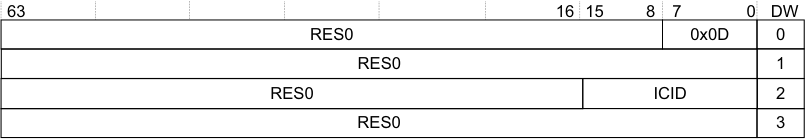
Image text
63 16 15 8 7 0 DW
RES0 0x0D 0
RES0 1
RES0 ICID 2
RES0 3
In Figure 5-10:
-
ICID specifies the interrupt collection.
-
DW is the doubleword offset within a 32 byte, or four doubleword, ITS command packet.
The command and its arguments are:
INVALL ICID
A command error occurs if any of the following apply:
-
The collection specified by ICID exceeds the maximum number supported by the ITS.
-
The collection specified by ICID has not been mapped to an RDbase using MAPC.
In this case, the ITS must take the actions described in Command errors.
The following pseudocode describes the operation of the INVALL command:
// ITS.INVALL // ==========
ITS.INVALL(ITSCommand cmd)
    if (CollectionOutOfRange(cmd.ICID))
    then if GITS_TYPER.SEIS == '1'
    then IMPLEMENTATION_DEFINED "SError INVALL_COLLECTION_OOR";
UNPREDICTABLE;
CollectionTableEntry cte = ReadCollectionTable(UInt(cmd.ICID));
if !cte.Valid then
    if GITS_TYPER.SEIS == '1' then
        IMPLEMENTATION_DEFINED "SError INVALL_UNMAPPED_COLLECTION";
        UNPREDICTABLE;
    // This invalidates any caches containing the configuration data
    for all interrupts in the
    // collection. Over invalidation is permitted.
    InvalidateCollectionCaches(UInt(cmd.ICID));
    IncrementReadPointer();
    return;
5.3.8 INVDB GICv4.1 only
In GICv4.1, the ITS command INVDB is allocated to invalidate the configuration of default doorbells:
Figure 5-11 shows the format of the INVDB command for GICv4.1 only.
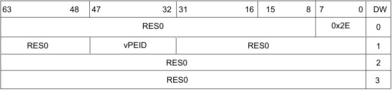
Image text
63 48 47 32 31 16 15 8 7 0 DW
RES0 0x2E 0
RES0 vPEID RES0 1
RES0 2
RES0 3
- vPEID = The vPEID of the vPE.
// ITS.INVDB // ========= ITS.INVDB(ITSCommand cmd)
if VCPUOutOfRange(cmd.VCPUID) then
    if GITS_TYPER.SEIS == 1 then
        IMPLEMENTATION_DEFINED "SError INVDB_VCPU_OOR";
        UNPREDICTABLE;
    VCPUTableEntry vte = ReadVCPUTable(UInt(cmd.VCPUID));
    if vte.Valid then InvalidateInterruptDoorbellCaches(VCPUID, vte);
    IncrementReadPointer();
    return;
INVDB is synchronized by a VSYNC command.
After completion of an INVDB command, there is no caching associated with the default doorbell of the specified vPE in any Redistributor.
A command error occurs if any of the following apply:
- An INVDB is issued with a vPEID that exceeds the configured maximum vPEID for the ITS: INVDB_VCPU_OOR (0x01_2E11).
An INVDB with a valid vPEID behaves as a NOP if either of the following points is true:
-
The vPEID is not mapped on the ITS.
-
The vPEID has no default doorbell.
5.3.9 MAPC
This command maps the Collection table entry defined by ICID to the target Redistributor, defined by RDbase.
Figure 5-12 shows the format of the MAPC command.
| 63 | 62 | 51 | 50 | 16 | 8 15 | 7 0 | DW | |||
|---|---|---|---|---|---|---|---|---|---|---|
| RES0 | 0x09 | 0 | ||||||||
| RES0 | 1 | |||||||||
| V | RES0 | RDbase | ICID | 2 | ||||||
| RES0 | 3 |
Figure 5-12 MAPC command format
In Figure 5-12:
-
V specifies whether RDbase is valid for the collection.
-
RDbase specifies the target Redistributor to which interrupts in the collection are forwarded. See IMPLEMENTATION DEFINED sizes in ITS command parameters.
-
ICID specifies the interrupt collection that is to be mapped.
-
DW is the doubleword offset within a 32 byte, or four doubleword, ITS command packet.
If GITS_TYPER.PTA == 1 and a physical address is specified, the target addresses must be 64KB aligned, meaning that only bits[47:16] are required. See IMPLEMENTATION DEFINED sizes in ITS command parameters for more information. In addition, when V is cleared to 0, this field must be written as zero, but hardware might ignore the value.
The command and its arguments are: MAPC ICID, RDbase, V
When V is 1:
-
Behavior is unpredictable if there are interrupts that are mapped to the specified collection and the collection is currently mapped to a Redistributor, unless MAPC is followed by MOVALL so that the pending state for the collection is moved from the old target Redistributor or the new target Redistributor. MOVALL might be issued by a different ITS:
-
Where multiple collections are remapped from the same source to the same destination, behavior is unpredictable if MOVALL is issued before all the MAPCs are globally observable.
-
Behavior is unpredictable if any ITS command that affects interrupts that belong to a remapped collection is issued after the MAPC, but before the MOVALL is globally observable.
-
-
Behavior is unpredictable if RDbase does not specify a valid Redistributor.
When V is 0:
-
MAPC removes the mapping of the specified interrupt collection. Interrupts for that are mapped to this collection are ignored.
-
Behavior is unpredictable if there are interrupts that are mapped to the specified collection, with the restriction that further translation requests from that device are ignored.
A command error occurs if the following applies:
- The collection specified by ICID exceeds the maximum number supported by the ITS.
In this case, the ITS must take the actions described in Command errors.
Note
When software uses a MAPC command to move a collection from targeting Redistributor A to targeting Redistributor B, it must issue a SYNC command to Redistributor A before issuing the accompanying MOVALL command. Otherwise, interrupts from the collection might still be taken by the PE associated with Redistributor A.
The following pseudocode describes the operation of the MAPC command:
// ITS.MAPC // ======== ITS.MAPC(ITSCommand cmd)
if CollectionOutOfRange(cmd.ICID) then
    if GITS_TYPER.SEIS == '1' then
        IMPLEMENTATION_DEFINED "SError MAPC_COLLECTION_OOR";
        UNPREDICTABLE;
    CollectionTableEntry cte;
    cte.Valid  = cmd.V == '1';
    cte.RDbase = cmd.RDbase;
    WriteCollectionTable(UInt(cmd.ICID), cte);
    IncrementReadPointer();
    return;
5.3.10 MAPD
This command maps the Device table entry associated with DeviceID to its associated ITT, defined by ITT_addr and Size.
Figure 5-13 shows the format of the MAPD command.
| 63 | 62 | 52 | 51 | 32 | 31 | 8 | 7 5 | 0 4 | DW | ||
|---|---|---|---|---|---|---|---|---|---|---|---|
| DeviceID | RES0 | 0x08 | 0 | ||||||||
| RES0 | Size | 1 | |||||||||
| V | RES0 | ITT_addr | RES0 | 2 | |||||||
| RES0 | 3 |
Figure 5-13 MAPD command format In Figure 5-13:
- DeviceID specifies the device that uses the ITT.
Note For more information about mapping devices to ITTs, see The Interrupt translation table.
-
V specifies whether the ITT_addr and Size fields are valid.
-
ITT_addr specifies bits[51:8] of the physical address of the ITT.
-
Size is a 5-bit number that specifies the supported number of bits for the device, minus one. The size field enables range checking of EventID for translation requests for this DeviceID.
-
DW is the doubleword offset within a 32 byte, or four doubleword, ITS command packet.
Behavior is UNPREDICTABLE if any of the following apply:
-
There is an existing mapping for the DeviceID and the mapped ITT contains valid EventID mappings.
-
When V == 1, the specified ITT does not contain all zeros.
The command and its arguments are:
MAPD DeviceID, ITT_addr, Size, V
The format of the ITT entries is IMPLEMENTATION DEFINED. A typical example entry size of 8 bytes permits allocation of identifiers to devices in multiples of 32 interrupts.
When V is 1:
-
MAPD associates a DeviceID with a 256 byte-aligned address of an ITT.
-
When V is 0:
-
MAPD removes the mapping for the specified DeviceID. Translation requests from that device are ignored.
-
MAPD removes the mapping of the specified DeviceID. and interrupt requests from that device are discarded. A subsequent translation for the DeviceID does not generate and LPI or VLPI until DeviceID has been mapped to the ITT again.
A command error occurs if any of the following apply:
-
DeviceID exceeds the maximum number of devices supported by an ITS.
-
Size exceeds the maximum value permitted by the settings of GITS_TYPER.ID_bits, when V is set to 1.
In this case, the ITS must take the actions described in Command errors.
Note ITS accesses to an ITT use the same Shareability and Cacheability attributes that are specified for the Device table, see The Device table.
The following pseudocode describes the operation of the MAPD command:
// ITS.MAPD // ======== ITS.MAPD(ITSCommand cmd)
    if DeviceOutOfRange(cmd.DeviceID)
    then if GITS_TYPER.SEIS == '1'
    then IMPLEMENTATION_DEFINED "SError MAPD_DEVICE_OOR";
UNPREDICTABLE;
if SizeOutOfRange(cmd.Size) then

if GITS_TYPER.SEIS == '1' then IMPLEMENTATION_DEFINED "SError MAPD_ITTSIZE_OOR"; UNPREDICTABLE;
// If a device is Re-mapped software must perform the following actions
// to ensure the LPI configuration is up to date:
// 1. Ensure that the device is quiescent and that all interrupts have
//     been handled.
// 2. Remap the device with the new (empty) ITT
//
DeviceTableEntry dte;
5.3.11 MAPI
This command maps the event defined by EventID and DeviceID into an ITT entry with ICID and pINTID = EventID.
Note
-
pINTID ≥0x2000 for a valid LPI INTID.
-
This is equivalent to MAPTI DeviceID, EventID, EventID, ICID
Figure 5-14 shows the format of the MAPI command.
| 63 | 32 | 31 | 16 | 8 15 | 7 0 | DW | ||
|---|---|---|---|---|---|---|---|---|
| DeviceID | RES0 | 0x0B | 0 | |||||
| RES0 | EventID | 1 | ||||||
| RES0 | ICID | 2 | ||||||
| RES0 | 3 |
Figure 5-14 MAPI command format
In Figure 5-14:
-
EventID identifies the interrupt, associated with a device, that is to be mapped.
-
DeviceID specifies the requesting device.
-
ICID specifies the interrupt collection that includes the specified interrupt.
-
DW is the doubleword offset within a 32 byte, or four doubleword, ITS command packet.
If there is an existing mapping for the EventID-DeviceID combination, behavior is UNPREDICTABLE.
The command and its arguments are:
MAPI DeviceID, EventID, ICID
A command error occurs if any of the following apply:
-
DeviceID exceeds the maximum value supported by the ITS.
-
The device specified by DeviceID is not mapped to an ITT, using MAPD.
-
ICID exceeds the maximum number of interrupt collections supported by an ITS. For more information, see The Collection table.
-
The EventID exceeds the maximum value allowed by the ITT. This value is specified by the Size field when the MAPD command is issued. • EventID does not specify a valid LPI identifier. See INTIDs. In this case, the ITS must take the actions described in Command errors. The following pseudocode describes the operation of the MAPI command:
// ITS.MAPI // ======== ITS.MAPI(ITSCommand cmd)
if DeviceOutOfRange(cmd.DeviceID) then
    if GITS_TYPER.SEIS == '1' then
        IMPLEMENTATION_DEFINED "SError MAPI_DEVICE_OOR";
        UNPREDICTABLE;
    if CollectionOutOfRange(cmd.ICID) then
        if GITS_TYPER.SEIS == '1' then
            IMPLEMENTATION_DEFINED "SError MAPI_COLLECTION_OOR";
            UNPREDICTABLE;
        DeviceTableEntry dte = ReadDeviceTable(UInt(cmd.DeviceID));
        if !dte.Valid then
            if GITS_TYPER.SEIS == '1' then
                IMPLEMENTATION_DEFINED "SError MAPI_UNMAPPED_DEVICE";
                UNPREDICTABLE;
            if IdOutOfRange(cmd.EventID, dte.ITT_size) then
                if GITS_TYPER.SEIS == '1' then
                    IMPLEMENTATION_DEFINED "SError MAPI_ID_OOR";
                    UNPREDICTABLE;
                if LPIOutOfRange(cmd.EventID) then
                    if GITS_TYPER.SEIS == '1' then
                        IMPLEMENTATION_DEFINED "SError MAPI_ID_OOR";
                        UNPREDICTABLE;
                    InterruptTableEntry ite = ReadTranslationTable(dte.ITT_base, UInt(cmd.EventID));
ite.Valid = TRUE; ite.Type = physical_interrupt; ite.OutputID = cmd.EventID; ite.DoorbellID = ZeroExtend(INTID_SPURIOUS); // Don’t generate a doorbell ite.ICID = cmd.ICID;
WriteTranslationTable(dte.ITT_base, UInt(cmd.EventID), ite);
IncrementReadPointer();
return;
5.3.12 MAPTI
This command maps the event defined by EventID and DeviceID to its associated ITE, defined by ICID and pINTID in the ITT associated with DeviceID.
Figure 5-15 shows the format of the MAPTI command.
| 63 | 32 | 31 | 16 | 8 15 | 7 0 | DW | ||
|---|---|---|---|---|---|---|---|---|
| DeviceID | RES0 | 0x0A | 0 | |||||
| pINTID | EventID | 1 | ||||||
| RES0 | ICID | 2 | ||||||
| RES0 | 3 |
Figure 5-15 MAPTI command format In Figure 5-15:
-
EventID identifies the interrupt, associated with a device, that is to be mapped.
-
pINTID is the INTID of the physical interrupt that is presented to software.
-
DeviceID specifies the requesting device.
-
ICID specifies the interrupt collection that includes the specified physical interrupt.
-
DW is the doubleword offset within a 32 byte, or four doubleword, ITS command packet.
If there is an existing mapping for the EventID-DeviceID combination, behavior is UNPREDICTABLE.
The command and its arguments are:
MAPTI DeviceID, EventID, pINTID, ICID
A command error occurs if any of the following apply:
-
DeviceID exceeds the maximum value supported by the ITS.
-
The device specified by DeviceID is not mapped to an ITT using MAPD.
-
The number of collections exceeds the maximum number of collections supported by the ITS. For more information, see The Collection table.
-
The EventID exceeds the maximum value allowed by the ITT. This value is specified by the Size field when the MAPD command is issued.
-
pINTID does not specify a valid LPI INTID. For information about the LPI INTID range, see INTIDs.
In this case, the ITS must take the actions described in Command errors.
The following pseudocode describes the operation of the MAPTI command:
// ITS.MAPTI // =========
ITS.MAPTI(ITSCommand cmd)
if DeviceOutOfRange(cmd.DeviceID) then
    if GITS_TYPER.SEIS == '1' then
        IMPLEMENTATION_DEFINED "SError MAPTI_DEVICE_OOR";
        UNPREDICTABLE;
    if CollectionOutOfRange(cmd.ICID) then
        if GITS_TYPER.SEIS == '1' then
            IMPLEMENTATION_DEFINED "SError MAPTI_COLLECTION_OOR";
            UNPREDICTABLE;
        DeviceTableEntry dte = ReadDeviceTable(UInt(cmd.DeviceID));
        if !dte.Valid then
            if GITS_TYPER.SEIS == '1' then
                IMPLEMENTATION_DEFINED "SError MAPTI_UNMAPPED_DEVICE";
                UNPREDICTABLE;
            if IdOutOfRange(cmd.EventID, dte.ITT_size) then
                if GITS_TYPER.SEIS == '1' then
                    IMPLEMENTATION_DEFINED "SError MAPTI_ID_OOR";
                    UNPREDICTABLE;
                if LPIOutOfRange(cmd.pINTID) then
                    if GITS_TYPER.SEIS == '1' then
                        IMPLEMENTATION_DEFINED "SError MAPTI_PHYSICALID_OOR";
                        UNPREDICTABLE;
                    InterruptTableEntry ite = ReadTranslationTable(dte.ITT_base, UInt(cmd.EventID));
ite.Valid = TRUE; ite.Type = physical_interrupt; ite.OutputID = cmd.pINTID; ite.DoorbellID = ZeroExtend(INTID_SPURIOUS); // Don’t generate a doorbell ite.ICID = cmd.ICID;
WriteTranslationTable(dte.ITT_base, UInt(cmd.EventID), ite);
IncrementReadPointer();
return;
5.3.13 MOVALL
This command instructs the Redistributor specified by RDbase1 to move all of its interrupts to the Redistributor specified by RDbase2.
Note Both the mapping of interrupts to collections and the mapping of collections to Redistributors are normally unaffected by this command. Software must ensure that any interrupts that might be affected by this command target the Redistributor specified by RDbase2, otherwise system behavior is UNPREDICTABLE. In particular, an implementation might choose to remap all affected collections to RDbase2.
Figure 5-16 shows the format of the MOVALL command.
| 63 | 51 | 50 | 32 | 31 | 16 | 8 15 | 7 0 | DW | |
|---|---|---|---|---|---|---|---|---|---|
| RES0 | 0x0E | 0 | |||||||
| RES0 | 1 | ||||||||
| RES0 | Rdbase 1 | RES0 | 2 | ||||||
| RES0 | Rdbase 2 | RES0 | 3 |
Figure 5-16 MOVALL command format
In Figure 5-16:
-
RDbase1 specifies the Redistributor with which the interrupts are currently associated. See IMPLEMENTATION DEFINED sizes in ITS command parameters.
-
RDbase2 specifies the Redistributor to which the interrupts are to be moved. See IMPLEMENTATION DEFINED sizes in ITS command parameters.
-
DW is the doubleword offset within a 32 byte, or four doubleword, ITS command packet.
The command and its arguments are:
MOVALL RDbase1, RDbase2
Behavior is unpredictable if RDbase1 and RDbase2 do not specify a valid Redistributor. The format of these fields is specified by GITS_TYPER.PTA.
MOVALL targeting a RD with LPIs disabled is CONSTRAINED UNPREDICTABLE, with a choice of:
-
Clear the pending state of all moved LPIs.
-
Act as NOP, with the pending state is unchanged on the source RD.
The following pseudocode describes the operation of the MOVALL command:
// ITS.MOVALL // ==========
ITS.MOVALL(ITSCommand cmd) rd1 = cmd.RD1base;
rd2 = cmd.RD2base;
if rd1 != rd2
    then MoveAllPendingState(rd1, rd2);
IncrementReadPointer();
return;
5.3.14 MOVI
This command updates the ICID field in the ITT entry for the event defined by DeviceID and EventID. It also translates the event defined by EventID and DeviceID into an ICID and pINTID, and instructs the appropriate Redistributor to move the pending state, if it is set, of the interrupt to the Redistributor defined by the new ICID, and to update the ITE associated with the event to use the new ICID.
Figure 5-17 shows the format of the MOVI command.
| 63 | 32 | 31 | 16 | 8 15 | 7 0 | DW | ||
|---|---|---|---|---|---|---|---|---|
| DeviceID | RES0 | 0x01 | 0 | |||||
| RES0 | EventID | 1 | ||||||
| RES0 | ICID | 2 | ||||||
| RES0 | 3 |
Figure 5-17 MOVI command format
In Figure 5-17:
-
EventID identifies the interrupt, associated with a device, that is to be redirected.
-
DeviceID specifies the requesting device.
-
ICID specifies the new interrupt collection that is to include the specified physical interrupt.
-
DW is the doubleword offset within a 32 byte, or four doubleword, ITS command packet.
The command and its arguments are:
MOVI DeviceID, EventID, ICID
A command error occurs if any of the following apply:
-
DeviceID exceeds the maximum value supported by the ITS.
-
The device specified by DeviceID is not mapped to an ITT, using MAPD.
-
ICID exceeds the maximum number of interrupt collections supported by an ITS.
-
ICID is not mapped to an RDbase using MAPC.
-
EventID is not mapped to a collection, using MAPI or MAPTI.
-
EventID corresponds to a virtual LPI.
In this case, the ITS must take the actions described in Command errors.
Note If, after using MOVI to move an interrupt from collection A to collection B, software moves the same interrupt again from collection B to collection C, a SYNC command must be used before the second MOVI for the Redistributor associated with collection A to ensure correct behavior.
When MOVI is issued targeting a Collection that is unmapped, or mapped to a Redistributor with LPIs disabled, behavior is CONSTRAINED UNPREDICTABLE, with a choice of:
-
Clear the pending state of the moved LPI.
-
Pending state unchanged on the source RD.
The following pseudocode describes the operation of the MOVI command:
// ITS.MOVI // ========
ITS.MOVI(ITSCommand cmd)
if DeviceOutOfRange(cmd.DeviceID) then
    if GITS_TYPER.SEIS == '1' then
        IMPLEMENTATION_DEFINED "SError MOVI_DEVICE_OOR";
        UNPREDICTABLE;
    if CollectionOutOfRange(cmd.ICID) then
        if GITS_TYPER.SEIS == '1' then
            IMPLEMENTATION_DEFINED "SError MOVI_COLLECTION_OOR";
            UNPREDICTABLE;
        DeviceTableEntry dte = ReadDeviceTable(UInt(cmd.DeviceID));
        if !dte.Valid then
            if GITS_TYPER.SEIS == '1' then
                IMPLEMENTATION_DEFINED "SError MOVI_UNMAPPED_DEVICE";
                UNPREDICTABLE;
            if IdOutOfRange(cmd.EventID, dte.ITT_size) then
                if GITS_TYPER.SEIS == '1' then
                    IMPLEMENTATION_DEFINED "SError MOVI_ID_OOR";
                    UNPREDICTABLE;
                InterruptTableEntry ite = ReadTranslationTable(dte.ITT_base, UInt(cmd.EventID));
                if !ite.Valid then
                    if GITS_TYPER.SEIS == '1' then
                        IMPLEMENTATION_DEFINED "SError MOVI_UNMAPPED_INTERRUPT";
                        IncrementReadPointer();
                        return;
                    if ite.Type == virtual_interrupt then
                        if GITS_TYPER.SEIS == '1' then
                            IMPLEMENTATION_DEFINED "SError MOVI_ID_IS_VIRTUAL";
                            UNPREDICTABLE;
                        CollectionTableEntry cte1 = ReadCollectionTable(UInt(ite.ICID));
                        if !cte1.Valid then
                            if GITS_TYPER.SEIS == '1' then
                                IMPLEMENTATION_DEFINED "SError MOVI_UNMAPPED_COLLECTION";
                                UNPREDICTABLE;
                            CollectionTableEntry cte2 = ReadCollectionTable(UInt(cmd.ICID));
                            if !cte2.Valid then
                                if GITS_TYPER.SEIS == '1' then
                                    IMPLEMENTATION_DEFINED "SError MOVI_UNMAPPED_COLLECTION";
                                    IncrementReadPointer();
                                    return;
                                bits(32) rd1 = cte1.RDbase;
                                bits(32) rd2 = cte2.RDbase;
                                if rd1 != rd2 then
                                    // Move the move the pending state to rd2
                                    if set taking care of any races where the
                                    // interrupt has been forwarded to the processor
                                    MovePendingState(rd1, rd2, ite.OutputID);
5.3.15 SYNC
This command ensures all outstanding ITS operations associated with physical interrupts for the Redistributor specified by RDbase are globally observed before any further ITS commands are executed. Following the execution of a SYNC, the effects of all previous commands must apply to subsequent writes to GITS_TRANSLATER.
Figure 5-18 shows the format of the SYNC command.
| 63 | 51 | 50 | 32 | 31 | 16 | 8 15 | 7 0 | DW | |
|---|---|---|---|---|---|---|---|---|---|
| RES0 | 0x05 | 0 | |||||||
| RES0 | 1 | ||||||||
| RES0 | RDbase | RES0 | 2 | ||||||
| RES0 | 3 |
Figure 5-18 SYNC command format In Figure 5-18:
-
RDbase specifies the physical address of the target Redistributor. The format of the target address is determined by GITS_TYPER.PTA. See IMPLEMENTATION DEFINED sizes in ITS command parameters for more information.
-
DW is the doubleword offset within a 32 byte, or four doubleword, ITS command packet.
The command and its arguments are:
SYNC RDbase
The following pseudocode describes the operation of the SYNC command:
// Wait for the external effects of any virtual commands to be observable by all redistributors
// and ensure the internal effects of any previous commands affect any subsequent interrupt
// requests or commands
WaitForVirtualCompletion(rd_base);

IncrementReadPointer();

return;
5.3.16 VINVALL
This command ensures that any cached Redistributor information associated with vPEID is consistent with the associated LPI Configuration tables held in memory.
This command is provided only in GICv4.
Figure 5-19 shows the format of the VINVALL command.
| 63 | 48 | 47 | 32 | 31 | 8 | 7 0 | DW | |
|---|---|---|---|---|---|---|---|---|
| RES0 | 0x2D | 0 | ||||||
| RES0 | vPEID | RES0 | 1 | |||||
| RES0 | 2 | |||||||
| RES0 | 3 |
Figure 5-19 VINVALL command format
In Figure 5-19:
-
vPEID specifies the vPE.
-
DW is the doubleword offset within a 32 byte, or four doubleword, ITS command packet.
The command and its arguments are:
VINVALL vPEID
A command error occurs if any of the following apply:
-
vPEID exceeds the maximum number supported by the ITS, as defined by GITS_BASER
. -
The PE specified by vPEID is not mapped to a Redistributor using VMAPP GICv4.0.
In this case, the ITS must take the actions described in Command errors. The following pseudocode describes the operation of the VINVALL command:
// ITS.VINVALL // ===========
ITS.VINVALL(ITSCommand cmd)
    if VCPUOutOfRange(cmd.VCPUID) then
if GITS_TYPER.SEIS == '1' then
    IMPLEMENTATION_DEFINED "SError VINVALL_VCPU_OOR";
    UNPREDICTABLE;
VCPUTableEntry vte = ReadVCPUTable(UInt(cmd.VCPUID));
if !vte.Valid then
    if GITS_TYPER.SEIS == '1' then
        IMPLEMENTATION_DEFINED "SError VINVALL_VCPU_INVALID";
        UNPREDICTABLE;
    InvalidateVCPUCaches(UInt(cmd.VCPUID));
    IncrementReadPointer();
    return;
5.3.17 VMAPI
This command maps the event defined by DeviceID and EventID into an ITT entry with vPEID, vINTID=EventID, and Dbell_PINTID, a doorbell provision.
Note
-
vINTID ≥0x2000 for a valid LPI INTID.
-
This is equivalent to VMAPTI DeviceID, EventID, EventID, pINTID, vPEID.
-
Dbell_pINTID must be either 1023 or Dbell_pINTID ≥0x2000 for a valid LPI INTID.
This command is provided only in GICv4.
Figure 5-20 shows the format of the VMAPI command.
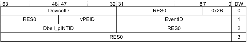
Image text
63 48 47 32 31 8 7 0 DW
DeviceID RES0 0x2B 0
RES0 vPEID EventID 1
Dbell_pINTID RES0 2
RES0 3
In Figure 5-20:
-
EventID identifies the interrupt, associated with a device, that is to be presented to the VM.
-
DeviceID specifies the requesting device.
-
vPEID specifies the vPE.
-
Dbell_pINTID specifies the ID that is presented to the hypervisor if the vPE is not scheduled.
- Note
If Dbell_pINTID indicates a spurious interrupt, then no physical interrupt is generated.
- DW is the doubleword offset within a 32 byte, or four doubleword, ITS command packet.
If there is an existing mapping for the EventID-DeviceID combination, behavior is UNPREDICTABLE.
The command and its arguments are:
VMAPI DeviceID, EventID, Dbell_pINTID, vPEID A command error occurs if any of the following apply:
-
DeviceID exceeds the maximum value supported by the ITS.
-
vPEID exceeds the maximum number supported by the ITS, as defined by GITS_BASER
. -
The device specified by DeviceID is not mapped to an ITT, using MAPD.
-
EventID exceeds the maximum value allowed by the ITT. This value is specified by the Size field when the MAPD command is issued.
-
EventID does not specify a valid LPI INTID. For information about valid LPI INTIDs, see INTIDs.
-
Dbell_pINTID does not specify a valid doorbell INTID, where a valid INTID is either: — 1023.
- Within the supported range for LPIs.
In this case, the ITS must take the actions described in Command errors.
The following pseudocode describes the operation of the VMAPI command:
// ITS.VMAPI // =========
ITS.VMAPI(ITSCommand cmd)
    if DeviceOutOfRange(cmd.DeviceID)
    then if GITS_TYPER.SEIS == '1'
    then IMPLEMENTATION_DEFINED "SError VMAPI_DEVICE_OOR";
UNPREDICTABLE;
if VCPUOutOfRange(cmd.VCPUID) then
    if GITS_TYPER.SEIS == '1' then
        IMPLEMENTATION_DEFINED "SError VMAPI_VCPU_OOR";
        UNPREDICTABLE;
    DeviceTableEntry dte = ReadDeviceTable(UInt(cmd.DeviceID));
    if !dte.Valid then
        if GITS_TYPER.SEIS == '1' then
            IMPLEMENTATION_DEFINED "SError VMAPI_UNMAPPED_DEVICE";
            UNPREDICTABLE;
        if IdOutOfRange(cmd.EventID, dte.ITT_size) then
            if GITS_TYPER.SEIS == '1' then
                IMPLEMENTATION_DEFINED "SError VMAPI_ID_OOR";
                UNPREDICTABLE;
            if LPIOutOfRange(cmd.EventID) then
                if GITS_TYPER.SEIS == '1' then
                    IMPLEMENTATION_DEFINED "SError VMAPI_ID_OOR";
                    UNPREDICTABLE;
                if LPIOutOfRange(cmd.Dbell_pINTID) then
                    if GITS_TYPER.SEIS == '1' then
                        IMPLEMENTATION_DEFINED "SError VMAPI_PHYSICALID_OOR";
                        UNPREDICTABLE;
                    InterruptTableEntry ite = ReadTranslationTable(dte.ITT_base, UInt(cmd.EventID));
ite.Valid = TRUE; ite.Type = virtual_interrupt; ite.OutputID = cmd.EventID; ite.DoorbellID = cmd.Dbell_pINTID; ite.VCPUID = cmd.VCPUID;
WriteTranslationTable(dte.ITT_base, UInt(cmd.EventID), ite);
IncrementReadPointer();
return;
5.3.18 VMAPP GICv4.0
This command maps the vPE table entry defined by vPEID to the target RDbase, including an associated virtual LPI Pending table (VPT_addr, VPT_size).
Figure 5-21 shows the format of the VMAPP command for GICv4.0.
| 63 | 62 | 51 | 50 | 32 | 31 | 16 | 8 15 | 7 5 | 0 4 | DW | |
|---|---|---|---|---|---|---|---|---|---|---|---|
| RES0 | 0x29 | 0 | |||||||||
| RES0 | vPEID | RES0 | 1 | ||||||||
| V | RES0 | RDbase | RES0 | 2 | |||||||
| RES0 | VPT_addr | RES0 | VPT_ size | 3 |
Figure 5-21 VMAPP GICv4.0 command format In Figure 5-21:
-
vPEID specifies the vPE.
-
V specifies whether the RDbase and VPT_addr are valid for the vPE.
-
RDbase specifies the target Redistributor that owns the vPE and to which the ITS directs commands for that PE. See IMPLEMENTATION DEFINED sizes in ITS command parameters.
-
VPT_addr specifies bits [51:16] of the physical address of the virtual LPI Pending table for the vPE.
Note The target addresses must be 64KB aligned, meaning that only bits [51:16] are required. Bits [15:0] of the physical address are 0.
-
VPT_size specifies the number of vINTID bits that the vPE supports, minus one.
-
DW is the doubleword offset within a 32 byte, or four doubleword, ITS command packet.
The command and its arguments are:
VMAPP vPEID, RDbase, VPT_addr, VPT_size, V
When V is 0:
- VMAPP removes the mapping for the specified vPE. Interrupts that are mapped to this vPE are discarded.
When V is 1:
- Behavior is UNPREDICTABLE if RDbase does not specify a valid Redistributor.
A command error occurs if any of the following apply:
-
vPEID exceeds the maximum number supported by the ITS, as defined by GITS_BASER
. -
Size exceeds the maximum value permitted by the settings of GITS_TYPER.ID_bits.
In this case, the ITS must take the actions described in Command errors.
Note If a system contains multiple ITSs, Arm strongly recommends that software does not issue a VMAPP when there is an outstanding VMOVP for the same vPEID on another ITS, as this could create a race condition.
The following pseudocode describes the operation of the VMAPP command:
// ITS.VMAPP // =========
ITS.VMAPP(ITSCommand cmd)
    if VCPUOutOfRange(cmd.VCPUID) then
if GITS_TYPER.SEIS == '1' then IMPLEMENTATION_DEFINED "SError VMAPP_VCPU_OOR"; UNPREDICTABLE;

VCPUTableEntry vte;
// Common to GICv4.0 and GICv4.1
vte.Valid = cmd.V == '1';
vte.RDbase = cmd.RDbase;

if HasGIC41Ext() then
    // GICv4.1

    if ((Uint(cmd.VPT_size) < 14) || ((Uint(GICD_TYPER.bits) > 23)) then
        if ConstrainUnpredictableBool() then
            (c, cmd.VPT_size) = ConstrainUnpredictableInteger(14, 24);
            assert (c == Constraint_UNKNOWN);

    // Record configuration in vPE Configuration Table,
    // held by Redistributors
    WriteVPEConfigurationTable(UInt(cmd.VCPUID), cmd.RDbase,
        cmd.VCONF_addr, cmd.VPT_addr,
        cmd.Default_Doorbell_pINTID, cmd.VPT_size,
        cmd.V, cmd.Alloc, cmd.PTZ);

    // The ITS could record the size of the VPT to detect out of range
    // INTIDs, or it could rely on the Redistributors doing this.
else
    // GICv4.0
    if SizeOutOfRange(cmd.VPT_size) then
        if GITS_TYPER.SEIS == '1' then IMPLEMENTATION_DEFINED "SError
            VMAPP_VPTSIZE_OOR";
        UNPREDICTABLE;
    vte.VPT_base = cmd.VPT_addr:Zeros(16);
    vte.VPT_size = cmd.VPT_size;

WriteVCPUTable(UInt(cmd.VCPUID), vte);

IncrementReadPointer();

return;
5.3.19 VMAPP GICv4.1
The VMAPP command is modified in GICv4.1 to allow the specifying of the LPI configuration of the vPE and pending table locations.
Figure 5-22 shows the format of the VMAPP command for GICv4.1.
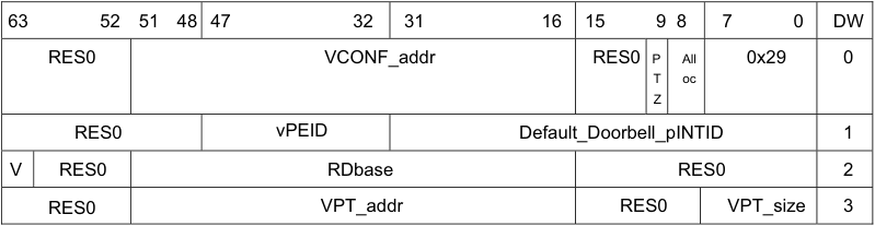
Image text
63 52 51 48 47 32 31 16 15 9 8 7 0 DW
RES0 VCONF_addr RES0 P All 0x29 0
T oc
Z
RES0 vPEID Default_Doorbell_pINTID 1
V RES0 RDbase RES0 2
RES0 VPT_addr RES0 VPT_size 3
In Figure 5-22:
-
RDbase = Identifies the target Redistributor. RES0 when V==0.
-
VCONF_addr = Bits [51:16] of the address of the vPE’s Virtual Configuration Table, bits [15:0] are 0. RES0 when V==0.
-
VPT_addr = Bits [51:16] of the address of the vPE’s Virtual Pending Table, bits [15:0] are 0. RES0 when V==0.
-
VPT_size = The number of bits of vINTID for the vPE. RES0 when V==0.
-
Default_Doorbell_pINTID is the default doorbell for the vPE. RES0 when V==0.
-
Alloc = Signifies whether this is the first map, or last unmap, for this vPEID.
-
PTZ = Signifies whether VPT_addr points at zeroed memory, ignored when V!=1 or Alloc!=1.
The command and its arguments are:
VMAPP vPEID, RDbase, VPT_addr, VPT_size, V
When V is 0:
- VMAPP removes the mapping for the specified vPE.
When V is 1:
- Behavior is UNPREDICTABLE if RDbase does not specify a valid Redistributor.
A command error occurs if any of the following apply:
-
vPEID exceeds the maximum number supported by the ITS, as defined by GITS_BASER
. -
Size exceeds the maximum value permitted by the settings of GITS_TYPER.ID_bits.
-
VMAPP with V==1 specifies a Default_Doorbell_pINTID value other than 1023 that is outside the implemented LPI range. The command error code reported is 0x01_2906 (VMAPP_PHYSICALID_OOR).
In this case, the ITS must take the actions described in Command errors.
Note If a system contains multiple ITSs, Arm strongly recommends that software does not issue a VMAPP when there is an outstanding VMOVP for the same vPEID on another ITS, as this could create a race condition.
For the pseudocode that describes the operation of this command, see VMAPP GICv4.0.
Use of of the V and Alloc fields
GICv4.1 introduces the vPE Configuration table, which is associated with the Redistributors that record the locations of the virtual LPI Configuration and Pending tables. This table is populated using the VMAPP command.
The Alloc field in a VMAPP command is used when vPEs are created or destroyed, to indicate when the vPE Configuration table entry should be updated.
A VMAPP with {V, Alloc}=={0, 1} cleans and invalidates any cached virtual Pending table and virtual Configuration table associated with the vPEID held in the GIC. Invalid use of the Alloc field can cause UNPREDICTABLE behavior, including continued access by the IRI.
For a VMAPP when V==1, VPT_size determines the size of the vINTID namespace, from which the size of the virtual Configuration and Pending tables are derived.
For a VMAPP with V==1, if VPT_size is greater than the supported INTID size, one of the following CONSTRAINED UNPREDICTABLE values are used:
-
The specified value.
-
An UNKNOWN value in range value.
A VMAPP with V==1, Default_Doorbell_pINTID==1023 indicates no default doorbell.
A VMAPP with V==1 that specifies one of the following values of Default_Doorbell_pINTID, causes UNPREDICTABLE behavior to occur:
-
The value is used for valid EventID or DeviceID mappings.
-
The value is for the default doorbell of an existing valid vPE.
A VMAPP with Alloc==0 indicates that there is an existing mapping on at least one ITS for the vPEID. If this is not true, the resulting behavior is UNPREDICTABLE. A VMAPP with {V, Alloc}=={1, 1} indicates that this is the first mapping of the vPEID, in any ITS. Setting {V, Alloc}=={1, 1} at any other time causes UNPREDICTABLE behavior.
A VMAPP with {V, Alloc}=={0, 1} indicates that this is the last mapping for the vPEID, in any ITS. Setting {V, Alloc}=={0, 1} at any other time causes UNPREDICTABLE behavior.
The virtual LPI Configuration table and virtual LPI Pending table are allocated to the IRI when VMAPP with {V, Alloc}=={1, 1} is issued, and remains allocated to the IRI until VMAPP with {V, Alloc}=={0, 1} is completed. Table 5-7 summarizes the effects of the V and Alloc field combinations.
Table 5-7 Effects of V and Alloc field combinations
| V | Alloc | Description |
|---|---|---|
| 0 | 0 | Unmapcommand, there is still at least one other ITS with a valid mapping. |
| 0 | 1 | Unmapcommand, no other ITS has a valid mapping. |
| 1 | 0 | Mapcommand, at least one other ITS already has this mapping. |
| 1 | 1 | Mapcommand, no other ITS has this mapping yet. |
Note UNPREDICTABLE behavior associated with the invalid use of Alloc can include the IRI continuing to read or write memory structures associated with the vPEID after release. Arm strongly recommends avoiding these cases.
A VMAPP with {V, Alloc}=={0, x} is self-synchronizing. This means the ITS command queue does not show the command as consumed until all of its effects are completed.
When multiple ITSs are implemented, issuing VMAPPs with V==1 for the same vPEID on different ITSs with different values of VCONF_addr, VPT_addr or VPT_size, causes UNPREDICTABLE behavior.
When multiple ITSs are implemented, issuing VMAPPs with {V, Alloc}=={1, 0} where Default_Doorbell_pINTID or RDbase does not match the currently configured value causes UNPREDICTABLE behavior.
When {V, Alloc}!={1, 1}, the PTZ bit is IGNORED.
When {V, Alloc, PTZ}=={1, 1, 0}:
-
The IMPLEMENTATION DEFINED region of the specified virtual Pending table must contain all zeros or have been populated by a GIC of the same implementation. Otherwise the behavior is UNPREDICTABLE.
-
The pending state and SGI configuration will be loaded by the IRI.
When {V, Alloc, PTZ}=={1, 1, 1}, the specified virtual Pending table must contain all zeros, otherwise the behavior is UNPREDICTABLE. This includes the SGI and IMPLEMENTATION DEFINED regions.
5.3.20 VMAPTI
This command maps the event defined by DeviceID and EventID into an ITT entry with vPEID and vINTID, and Dbell_pINTID, a doorbell provision.
Note
-
vINTID ≥0x2000 for a valid LPI INTID.
-
Dbell_pINTID must be either 1023 or Dbell_pINTID ≥0x2000 for a valid LPI INTID.
This command is provided only in GICv4.
Figure 5-23 shows the format of the VMAPTI command.
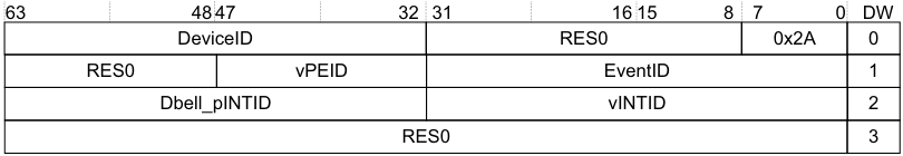
Image text
63 48 47 32 31 16 15 8 7 0 DW
DeviceID RES0 0x2A 0
RES0 vPEID EventID 1
Dbell_pINTID vINTID 2
RES0 3
In Figure 5-23:
-
vPEID specifies the vPE.
-
DeviceID specifies a device owned by the vPE.
-
vINTID specifies the INTID presented to the vPE that controls the device that DeviceID specifies.
-
Dbell_pINTID specifies the pINTID that is presented to the PE if the vPE is not scheduled.
Note If Dbell_pINTID is 1023 then no physical interrupt is generated.
- DW is the doubleword offset within a 32 byte, or four doubleword, ITS command packet.
If there is an existing mapping for the EventID-DeviceID combination, behavior is UNPREDICTABLE.
The command and its arguments are:
VMAPTI DeviceID, EventID, vINTID, Dbell_pINTID, vPEID
A command error occurs if any of the following apply:
-
DeviceID exceeds the maximum value supported by the ITS.
-
vPEID exceeds the maximum number supported by the ITS, as defined by GITS_BASER
. -
The device specified by DeviceID is not mapped to an ITT, using MAPD.
-
The EventID exceeds the maximum value allowed by the ITT. This value is specified by the Size field when the MAPD command is issued.
-
vINTID does not specify a valid LPI INTID, see INTIDs.
-
Dbell_pINTID does not specify a valid doorbell INTID, where a valid INTID is either: — 1023.
- Within the supported range for LPIs.
In this case, the ITS must take the actions described in Command errors.
The following pseudocode describes the operation of the VMAPTI command:
// ITS.VMAPTI // ==========
ITS.VMAPTI(ITSCommand cmd)
    if DeviceOutOfRange(cmd.DeviceID)
    then if GITS_TYPER.SEIS == '1'
    then IMPLEMENTATION_DEFINED "SError VMAPTI_DEVICE_OOR";
UNPREDICTABLE;
if VCPUOutOfRange(cmd.VCPUID) then
    if GITS_TYPER.SEIS == '1' then
        IMPLEMENTATION_DEFINED "SError VMAPTI_VCPU_OOR";
        UNPREDICTABLE;
    DeviceTableEntry dte = ReadDeviceTable(UInt(cmd.DeviceID));
    if !dte.Valid then
        if GITS_TYPER.SEIS == '1' then
            IMPLEMENTATION_DEFINED "SError VMAPTI_UNMAPPED_DEVICE";
            UNPREDICTABLE;
        if IdOutOfRange(cmd.EventID, dte.ITT_size) then
            if GITS_TYPER.SEIS == '1' then
                IMPLEMENTATION_DEFINED "SError VMAPTI_ID_OOR";
                UNPREDICTABLE;
            if LPIOutOfRange(cmd.vINTID) then
                if GITS_TYPER.SEIS == '1' then
                    IMPLEMENTATION_DEFINED "SError VMAPTI_VIRTUALID_OOR";
                    IncrementReadPointer();
                    return;
                if LPIOutOfRange(cmd.pINTID) then
                    if GITS_TYPER.SEIS == '1' then
                        IMPLEMENTATION_DEFINED "SError VMAPTI_PHYSICALID_OOR";
                        UNPREDICTABLE;
                    InterruptTableEntry ite = ReadTranslationTable(dte.ITT_base, UInt(cmd.EventID));
ite.Valid = TRUE; ite.Type = virtual_interrupt; ite.OutputID = cmd.vINTID; ite.DoorbellID = cmd.Dbell_pINTID; ite.VCPUID = cmd.VCPUID;
WriteTranslationTable(dte.ITT_base, UInt(cmd.EventID), ite);
IncrementReadPointer();
return;
5.3.21 VMOVI
This command updates the vPEID field in the ITT entry for the event defined by DeviceID and EventID. It also translates the event defined by EventID and DeviceID into a vPEID and pINTID, and instructs the appropriate Redistributor to move the pending state of the interrupt to the Redistributor defined by the new vPEID, and updates the ITE associated with the event to use the new vPEID.
This command is provided only in GICv4.
Figure 5-24 shows the format of the VMOVI command.
| 63 | 48 | 47 | 32 | 31 | 8 | 7 1 | 0 | DW | |
|---|---|---|---|---|---|---|---|---|---|
| DeviceID | RES0 | 0x21 | 0 | ||||||
| RES0 | vPEID | EventID | 1 | ||||||
| Dbell_pINTID | RES0 | D | 2 | ||||||
| RES0 | 3 |
Figure 5-24 VMOVI command format
In Figure 5-24:
-
vPEID specifies the vPE.
-
EventID identifies the interrupt, associated with a device and already mapped by the ITS, that is to be moved to a new target specified by vPEID.
-
D specifies whether the Dbell_pINTID field is valid.
-
DeviceID specifies the device that generates the interrupt.
-
Dbell_pINTID specifies the ID that is presented to the hypervisor if the vPE is not scheduled.
Note
If Dbell_pINTID is 1023 then no physical interrupt is generated.
- DW is the doubleword offset within a 32 byte, or four doubleword, ITS command packet.
The command and its arguments are:
VMOVI DeviceID, EventID, vPEID, [Dbell_pINTID]
A command error occurs if any of the following apply:
-
DeviceID exceeds the maximum value supported by the ITS.
-
vPEID exceeds the maximum number supported by the ITS, as defined by GITS_BASER
. -
The device specified by DeviceID is not mapped to an ITT, using MAPD.
-
The EventID exceeds the maximum value allowed by the ITT. This value is specified by the Size field when the MAPD command is issued.
-
The vPE is not mapped to a Redistributor, using VMAPP GICv4.0.
-
EventID corresponds to a physical LPI.
-
If D is 1 and pINTID does not specify a valid doorbell INTID, where a valid INTID is either: — 1023.
- Within the supported range for LPIs.
In this case, the ITS must take the actions described in Command errors.
Note If, after using VMOVI to move an interrupt from vPE A to vPE B, software moves the same interrupt again, a VSYNC command must be issued to vPE A between the moves to ensure correct behavior.
When VMOVI is issued targeting a vPE that is unmapped, or mapped to a Redistributor with LPIs disabled, behavior is CONSTRAINED UNPREDICTABLE with a choice of:
-
Clear the pending state of the moved LPI.
-
Pending state unchanged on the source vPE.
The following pseudocode describes the operation of the VMOVI command:
// ITS.VMOVI

// =========
ITS.VMOVI(ITSCommand cmd)
if DeviceOutOfRange(cmd.DeviceID) then
    if GITS_TYPER.SEIS == '1' then
        IMPLEMENTATION_DEFINED "SError VMOVI_DEVICE_OOR";
        UNPREDICTABLE;
    if VCPUOutOfRange(cmd.VCPUID) then
        if GITS_TYPER.SEIS == '1' then
            IMPLEMENTATION_DEFINED "SError VMOVI_VCPU_OOR";
            UNPREDICTABLE;
        if ( cmd.V == '1' && LPIOutOfRange(cmd.pINTID) && cmd.pINTID != '1023') then
            if GITS_TYPER.SEIS == '1' then
                IMPLEMENTATION_DEFINED "SError VMOVI_PHYSICALID_OOR";
                UNPREDICTABLE;
            DeviceTableEntry dte = ReadDeviceTable(UInt(cmd.DeviceID));
            if !dte.Valid then
                if GITS_TYPER.SEIS == '1' then
                    IMPLEMENTATION_DEFINED "SError VMOVI_UNMAPPED_DEVICE";
                    UNPREDICTABLE;
                if IdOutOfRange(cmd.EventID, dte.ITT_size) then
                    if GITS_TYPER.SEIS == '1' then
                        IMPLEMENTATION_DEFINED "SError VMOVI_ID_OOR";
                        UNPREDICTABLE;
                    InterruptTableEntry ite = ReadTranslationTable(dte.ITT_base, UInt(cmd.EventID));
                    if !ite.Valid then
                        if GITS_TYPER.SEIS == '1' then
                            IMPLEMENTATION_DEFINED "SError VMOVI_UNMAPPED_INTERRUPT";
                            UNPREDICTABLE;
                        if ite.Type == physical_interrupt then
                            if GITS_TYPER.SEIS == '1' then
                                IMPLEMENTATION_DEFINED "SError VMOVI_ID_IS_PHYSICAL";
                                UNPREDICTABLE;
                            VCPUTableEntry vte1 = ReadVCPUTable(UInt(ite.VCPUID));
                            VCPUTableEntry vte2 = ReadVCPUTable(UInt(cmd.VCPUID));
                            if !vte1.Valid then
                                if GITS_TYPER.SEIS == '1' then
                                    IMPLEMENTATION_DEFINED "SError VMOVI_ITEVCPU_INVALID";
                                    UNPREDICTABLE;
                                if !vte2.Valid then
                                    if GITS_TYPER.SEIS == '1' then
                                        IMPLEMENTATION_DEFINED "SError VMOVI_CMDVCPU_INVALID";
                                        UNPREDICTABLE;
                                    bits(32) rd1 = vte1.RDbase;
                                    Address vpt1 = vte1.VPT_base;
                                    bits(32) rd2 = vte2.RDbase;
                                    Address vpt2 = vte2.VPT_base;
ite.VCPUID = cmd.VCPUID;
// From this point new interrupts sent to the new VCPU move the pending
// state to rd2 if set taking care of any races where the interrupt
// has been forwarded to the processor
MoveVirtualPendingState(rd1, vpt1, vpt2, ite.OutputID);

IncrementReadPointer();

return;
5.3.22 VMOVP GICv4.0
This command updates the vPE table entry defined by vPEID to the target RDbase. Software must use SequenceNumber and ITSList to synchronize the execution of VMOVP commands across more than one ITS.
This command is provided only in GICv4.
Software must ensure that this command is not executed with a vPEID that is scheduled on the target Redistributor, otherwise system behavior is UNPREDICTABLE.
Figure 5-25 shows the format of the VMOVP command.
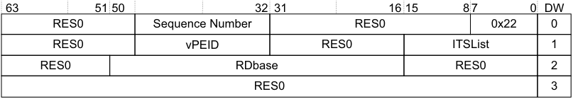
Image text
63 51 50 32 31 16 15 8 7 0 DW
RES0 Sequence Number RES0 0x22 0
RES0 vPEID RES0 ITSList 1
RES0 RDbase RES0 2
RES0 3
In Figure 5-25:
-
vPEID specifies the vPE.
-
RDbase specifies the Redistributor to which interrupts are forwarded. See IMPLEMENTATION DEFINED sizes in ITS command parameters.
-
Sequence Number specifies the identity of the synchronization point that every ITS included in ITS List uses. When GITS_TYPER.VMOVP == 0 Sequence Number specifies the identity of the synchronization point that is used by all ITSs that are included in ITSList.
-
When GITS_TYPER.VMOVP == 1 Sequence Number is RES0.
-
For more information, see VMOVP usage.
-
-
ITSList specifies the ITS instances that are included in the synchronization operation, where:
-
Each bit in ITS List identifies an ITS where bit[n] corresponds to ITS n.
-
An ITS is included if the corresponding bit is set to 1. When GITS_TYPER.VMOVP == 0 ITSList specifies which ITSs are included in the synchronization operation. Each bit of ITSList corresponds to an ITS, for example bit[0] of ITSList corresponds to ITS 0, bit[1] to ITS 1.
-
When GITS_TYPER.VMOVP ==1 ITSList is res0.
- DW is the doubleword offset within a 32 byte, or four doubleword, ITS command packet.
The command and its arguments are:
VMOVP, vPEID, RDbase, SequenceNumber, ITSList
A command error occurs if any of the following apply:
-
If the PE specified by vPEID is not mapped to a Redistributor, using VMAPP GICv4.0.
-
vPEID exceeds the maximum number supported by the ITS, as defined by GITS_BASER
.
In this case, the ITS must take the actions described in Command errors.
The following pseudocode describes the operation of the VMOVP command:
// ITS.VMOVP // ========= ITS.VMOVP(ITSCommand cmd)
if VCPUOutOfRange(cmd.VCPUID) then
    if GITS_TYPER.SEIS == '1' then
        IMPLEMENTATION_DEFINED "SError VMOVP_VCPU_OOR";
        UNPREDICTABLE;
    VCPUTableEntry vte = ReadVCPUTable(UInt(cmd.VCPUID));
    if !vte.Valid then
        if GITS_TYPER.SEIS == '1' then
            IMPLEMENTATION_DEFINED "SError VMOVP_VCPU_INVALID";
            UNPREDICTABLE;
vte.RDbase = cmd.RDbase;
if HasGIC41Ext() then UpdateVPEConfigurationTable(UInt(cmd.VCPUID), cmd.RDbase, cmd.Default_Doorbell_pINTID);

WriteVCPUTable(UInt(cmd.VCPUID), vte);

IncrementReadPointer();

return;
VMOVP usage
Where more than one ITS controls interrupts for the same vPE, moving this vPE must be coordinated between the different ITSs. This is controlled by software using one of the two approaches detailed here:
When GITS_TYPER.VMOVP == 0:
-
The VMOVP command must be issued for each ITS that controls interrupts for the vPE that is being moved. Each of these commands must have a common sequence number. That sequence number cannot be used for other VMOVP commands until all commands that previously used that sequence number have been processed by all ITSs.
-
The VMOVP command issued for each ITS contains a list of all the ITSs that are affected by moving the vPE. This is the ITS List.
-
Each ITS must have the sequence numbers presented to it in the same order in that they are presented to the other ITSs. When GITS_TYPER.VMOVP == 1:
-
The VMOVP command must be issued on only one of the ITSs that controls interrupts for the vPE that is being moved.
-
The implementation is responsible for propagating the updated mapping.
Not following this approach results in UNPREDICTABLE behavior.
Note If a system contains multiple ITSs, Arm strongly recommends that software does not issue a VMAPP when there is an outstanding VMOVP for the same vPEID on another ITS, as this could create a race condition.
5.3.23 VMOVP GICv4.1
The VMOVP command is modified in GICv4.1 to allow a Default Doorbell to be assigned to the vPE.
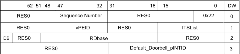
Image text
52 51 48 47 32 31 16 15 0 DW
RES0 Sequence Number RES0 0x22 0
RES0 vPEID RES0 ITSList 1
DB RES0 RDbase RES0 2
RES0 Default_Doorbell_pINTID 3
In Figure 5-26:
-
Default_Doorbell_pINTID is the default doorbell for the vPE.
-
DB signifies whether to mark the vPE as requiring a Default Doorbell on the target.
A VMOVP, Default_Doorbell_pINTID==1023 means no default doorbell. For a VMOVP with a valid Default_Doorbell_pINTID, other than 1023, the pending state of the default doorbell is transferred to the new target.
A VMOVP with Default_Doorbell_pINTID==1023 clears the pending state of the default doorbell on the old target if one was previously specified. The pending state of the default doorbell is transferred even when the INTID used for the doorbell is changed. Moving a vPE does not change the rules on generating default doorbells.
When VMOVP is issued, if DB==1, the vPE is marked as requesting Default Doorbell generation on the new target. When DB==0, the vPE is marked as not requesting Default Doorbell generation on the new target.
A command error occurs if any of the following apply:
-
The PE specified by vPEID is not mapped to a Redistributor, using VMAPP.
-
vPEID exceeds the maximum number supported by the ITS, as defined by GITS_BASER
. -
A VMOVP specifies a value of Default_Doorbell_pINTID outside of the implemented LPI range, other than 1023. The command error code reported is 0x01_2206(VMOVP_PHYSICALID_OOR).
In this case, the ITS must take the actions described in Command errors.
VMOVP usage in GICv4.1
VMOVP usage in GICv4.1 is the same as in GICv4.0. See VMOVP usage for more information.
5.3.24 VSGI for GICv4.1 only
The vSGI command sets the configuration of a specified vSGI and optionally clears its pending state.
Figure 5-27 shows the format of the vSGI command.
| 63 48 | 32 47 36 35 | 32 47 36 35 | 31 20 24 23:20 19: | 31 20 24 23:20 19: | 31 20 24 23:20 19: | 8 15:11 9 10 | 8 15:11 9 10 | 8 15:11 9 10 | 8 15:11 9 10 | 7 0 | DW |
|---|---|---|---|---|---|---|---|---|---|---|---|
| RES0 | vINTID | RES0 | Pri | RES0 | RES0 | G | C | E | 0x23 | 0 | |
| RES0 | vPEID | RES0 | 1 | ||||||||
| RES0 | 2 | ||||||||||
| RES0 | 3 |
Figure 5-27 vSGI command encoding
Where:
-
E is the enable configuration.
- Ignored when C==1.
-
G is the group configuration.
- Ignored when C==1.
-
Priority, records bits [7:4] of the priority configuration.
-
Bits [3:0] are treated as 0b0000.
-
Ignored when C==1.
-
-
vINTID and vPEID identify the interrupt.
-
C is used to indicate whether the pending state of the interrupt should be cleared.
The following pseudocode describes the operation of the VSGI command:
// ITS.VSGI // =========
ITS.VSGI(ITSCommand cmd)
    if VCPUOutOfRange(cmd.VCPUID)
    then if GITS_TYPER.SEIS == '1'
    then IMPLEMENTATION_DEFINED "SError VSGI_VCPU_OOR";
UNPREDICTABLE;
VCPUTableEntry vte = ReadVCPUTable(UInt(cmd.VCPUID));
// It is CONSTRAINED UNPREDICTABLE whether ReadVCPUTable() can
// return mappings from other ITSs when mapping exists on current
// current ITS

if Valid then
   if (CMD.C==0) then
        // Set configuration of interrupt
        SetVirtualSGIConfiguration(cmd.VCPUID, vte, cmd.Intid, cmd.E, cmd.Priority, cmd.G);
   else
        // Clear pending state of interrupt
        ClearVirtualSGIPendingState(VCPUID, vte, cmdIntid);

IncrementReadPointer();
return;
5.3.25 VSYNC
This command ensures all outstanding ITS operations for the vPEID specified are globally observed before any further ITS commands are executed. Following the execution of a VSYNC the effects of all previous commands must apply to subsequent writes to GITS_TRANSLATER.
This command is provided only in GICv4.
Figure 5-28 shows the format of the VSYNC command.
| 63 | 48 | 47 | 32 | 31 | 8 | 7 0 | DW | |
|---|---|---|---|---|---|---|---|---|
| RES0 | 0x25 | 0 | ||||||
| RES0 | vPEID | RES0 | 1 | |||||
| RES0 | 2 | |||||||
| RES0 | 3 |
Figure 5-28 VSYNC command format
In Figure 5-28:
-
vPEID specifies the vPE for which commands must be synchronized.
-
DW is the doubleword offset within a 32 byte, or four doubleword, ITS command packet.
The command and its arguments are:
VSYNC vPEID
A command error occurs if any of the following apply:
-
If the PE specified by vPEID is not mapped to a Redistributor, using VMAPP GICv4.0.
-
vPEID exceeds the maximum number supported by the ITS, as defined by GITS_BASER
.
In this case, the ITS must take the actions described in Command errors.
The following pseudocode describes the operation of the VSYNC command:
// ITS.VSYNC // ========= ITS.VSYNC(ITSCommand cmd)
    if VCPUOutOfRange(cmd.VCPUID)
    then if GITS_TYPER.SEIS == '1'
    then IMPLEMENTATION_DEFINED "SError VSYNC_VCPU_OOR";
UNPREDICTABLE;

VCPUTableEntry vte = ReadVCPUTable(UInt(cmd.VCPUID));

if !vte.Valid then if GITS_TYPER.SEIS == '1' then IMPLEMENTATION_DEFINED "SError VSYNC_VCPU_INVALID"; UNPREDICTABLE;

bits(32) rd_base = vte.RDbase;

// Wait
    for the external effects of any virtual commands to be observable by all redistributors
// and ensure the internal effects of any previous commands affect any subsequent interrupt
// requests or commands WaitForVirtualCompletion(rd_base);

IncrementReadPointer();

return;
5.4 Common ITS pseudocode functions
The following terminology appears in some of the pseudocode functions in this section:
Interrupt Translation
An action that causes the ITS to attempt to set a particular pending bit in a particular table. Pending Interrupt
A particular pending bit is set in a particular table.
The pseudocode functions in this section are based on the following assumptions:
-
Each ITS function must be performed as an atomic operation. Implementations must ensure that the observed behavior is consistent with that from a strictly atomic implementation.
-
Where the pseudocode issues a sequence of read and write operations to a particular Redistributor, these operations must be performed in the order in which they were generated.
-
Where the pseudocode issues a write to a particular Redistributor, operation does not need to wait for the completion of the write.
-
Where the pseudocode issues write to memory to update a table, operation does not need to wait for the completion of these writes. A write to memory might never become visible to an external observer. However, the effect of any such writes must be ordered by any subsequent ITS operations, including the handling of interrupt translations. There are no ordering rules other than the standard rule that memory must appear as if writes to each location occurred in program order.
-
Because each ITS function is performed as an atomic operation, any new interrupt translation that occurs after the function must be subject to the effects of that function.
-
The effects of caching of the Redistributor LPI Configuration and LPI Pending tables are specified explicitly in the pseudocode.
-
An interrupt translation might set a pending bit and pending bits remain set until handled by the PE. While an interrupt is pending it might be affected by an interrupt translation that is updated by a subsequent ITS function.
Note Some variable names used in the pseudocode differ from those used in the body text. For a list of the affected variables, see _Pseudocode terminology_B-910.
The following pseudocode invalidates any associated caching for the LPI configuration in the Redistributor for the specified translation.
// InvalidateByITE
// ===============
boolean InvalidateByITE(InterruptTableEntry ite)
if ite.Type == physical_interrupt then
    CollectionTableEntry cte = ReadCollectionTable(UInt(ite.ICID));
    if !cte.Valid then
        return FALSE;
    InvalidateInterruptCaches(ite.ICID, ite.OutputID);
else

VCPUTableEntry vte = ReadVCPUTable(UInt(ite.VCPUID));
if !vte.Valid then
    return FALSE;
InvalidateVirtualInterruptCaches(ite.VCPUID, ite.OutputID);
return TRUE;
The following pseudocode describes moving a pending interrupt.
The following pseudocode describes moving a pending interrupt.
// MovePendingState()
// ==================

MovePendingState(bits(32) rd1, bits(32) rd2, bits(32) ID)
    if IsPending(GICR_PENDBASER[rd1], ID) then
        // The interrupt is pending in the source redistributor

        // Make sure the interrupt is released or taken by the processor for
        // example by sending a clear and waiting for the response
        EnsureInterruptNotPendingOnProcessor(rd1, ID);

        if IsPending(GICR_PENDBASER[rd1], ID) then
            // The CPU released the interrupt and it is still pending
            // Note: the following must be done without any possibility of the
            // source redistributor re-forwarding the interrupt to the processor
            ClearPendingStateLocal(GICR_PENDBASER[rd1], ID);
            SetPendingStateLocal(GICR_PENDBASER[rd2], ID);

The following pseudocode describes moving a pending virtual interrupt.

// MoveVirtualPendingState()
// =========================

MoveVirtualPendingState(bits(32) rd_base, Address vpt1, Address vpt2, bits(32) ID)
    if IsPending(vpt1, ID) then
        // The interrupt is pending in the source redistributor

        // Make sure the interrupt is released or taken by the processor for example by sending a
        // VClear and waiting for the response
        EnsureVirtualInterruptNotPendingOnProcessor(rd_base, vpt1, ID);

        if IsPending(vpt1, ID) then
            // The CPU released the interrupt and it is still pending
            // Note: the following must be done without any possibility of the source redistributor
            // re-forwarding the interrupt to the processor
            ClearVirtualPendingStateLocal(vpt1, ID);
            SetVirtualPendingStateLocal(vpt2, ID);
    return;

The following pseudocode describes invalidating the caching of configuration data for the default doorbell
associated with a vPE.

// Invalidates any caching of configuration for the default
// doorbell associated with a vPE
InvalidateInterruptDoorbellCaches(UInt VCPUID, VCPUTableEntry vte);

// Sets the configuration of the specified vSGI
SetVirtualSGIConfiguration(UInt VCPUID, VCPUTableEntry vte, UInt Intid,
                           UInt Enable, UInt Priority, UInt Group);

// Clears the pending state of the specified vSGI
ClearVirtualSGIPendingState(UInt VCPUID, VCPUTableEntry vte, UInt Intid);

// Returns TRUE if the ITS supports GICv4.1
Boolean HasGIC41Ext();
The following pseudocode describes moving a pending virtual interrupt.
// MoveVirtualPendingState() // =========================
// The names of the Banked core registers.

enumeration RName {RName_0usr, RName_1usr, RName_2usr, RName_3usr, RName_4usr, RName_5usr,
                   RName_6usr, RName_7usr, RName_8usr, RName_8fiq, RName_9usr, RName_9fiq,
                   RName_10usr, RName_10fiq, RName_11usr, RName_11fiq, RName_12usr, RName_12fiq,
                   RName_SPusr, RName_SPfiq, RName_SPirq, RName_SPsvc,
                   RName_SPabt, RName_SPund, RName_SPmon, RName_SPhyp,
                   RName_LRusr, RName_LRfiq, RName_LRirq, RName_LRsvc,
                   RName_LRabt, RName_LRund, RName_LRmon,
                   RName_PC};

array bits(8) _Memory[0..0xFFFFFFFF];

Arrays are always explicitly declared, and there is no notation for a constant array. Arrays always contain at least
one element, because:
•      Enumerations always contain at least one symbolic constant.
•      Integer ranges always contain at least one integer.

Arrays do not usually appear directly in pseudocode. The items that syntactically look like arrays in pseudocode are
usually array-like functions such as R[i], MemU[address, size] or Elem[vector, i, size]. These functions package
up and abstract additional operations normally performed on accesses to the underlying arrays, such as register
banking, memory protection, endian-dependent byte ordering, exclusive-access housekeeping and Advanced SIMD
element processing.
The following pseudocode describes invalidating the caching of configuration data for the default doorbell associated with a vPE.
// Invalidates any caching of configuration for interrupts which are
// members of the collection specified by "collection"

InvalidateCollectionCaches(integer collection);
5.4.1 ITS helper functions
This subsection describes the ITS helper functions. These functions are placeholder functions for behavior that is not architected and that is IMPLEMENTATION DEFINED.
The functions are indicated by the hierarchical path names, for example shared/gic/its/its_helper:
-
shared/gic/its/its_helper/Address.
-
shared/gic/its/its_helper/ClearPendingState.
-
shared/gic/its/its_helper/ClearPendingStateLocal.
-
shared/gic/its/its_helper/CollectionOutOfRange.
-
shared/gic/its/its_helper/CollectionTableEntry.
-
shared/gic/its/its_helper/DeviceOutOfRange.
-
shared/gic/its/its_helper/DeviceTableEntry.
-
shared/gic/its/its_helper/EndOfCommand.
-
shared/gic/its/its_helper/EnsureInterruptNotPendingOnProcessor.
-
shared/gic/its/its_helper/EnsureVirtualInterruptNotPendingOnProcessor.
-
shared/gic/its/its_helper/IdOutOfRange.
-
shared/gic/its/its_helper/IncrementReadPointer.
-
shared/gic/its/its_helper/InterruptTableEntry.
-
shared/gic/its/its_helper/InterruptType.
-
shared/gic/its/its_helper/InterruptType.
-
shared/gic/its/its_helper/InvalidateInterruptCaches.
-
shared/gic/its/its_helper/InvalidateInterruptConfigurationCaches.
-
shared/gic/its/its_helper/InvalidateVCPUCaches.
-
shared/gic/its/its_helper/InvalidateVirtualConfigurationCaches.
-
shared/gic/its/its_helper/InvalidateVirtualInterruptCaches.
-
shared/gic/its/its_helper/IsPending.
-
shared/gic/its/its_helper/IsPending.
-
shared/gic/its/its_helper/LPIOutOfRange.
-
shared/gic/its/its_helper/MoveAllPendingState.
-
shared/gic/its/its_helper/ReadCollectionTable.
-
shared/gic/its/its_helper/ReadDeviceTable.
-
shared/gic/its/its_helper/ReadTranslationTable.
-
shared/gic/its/its_helper/ReadVCPUTable.
-
shared/gic/its/its_helper/RetargetVirtualInterrupt.
-
• shared/gic/its/its_helper/SetPendingState.
-
shared/gic/its/its_helper/SetPendingStateLocal.
-
shared/gic/its/its_helper/SizeOutOfRange.
-
shared/gic/its/its_helper/VCPUOutOfRange.
-
shared/gic/its/its_helper/VCPUTableEntry.
-
shared/gic/its/its_helper/WaitForCompletion.
-
shared/gic/its/its_helper/WaitForVirtualCompletion.
-
• shared/gic/its/its_helper/WriteCollectionTable. • shared/gic/its/its_helper/WriteDeviceTable.
-
shared/gic/its/its_helper/WriteTranslationTable.
-
• shared/gic/its/its_helper/WriteVCPUTable.
shared/gic/its/its_helper/Address
// Address()
// ============

type Address = bits(48);
shared/gic/its/its_helper/ClearPendingState
// ClearPendingState()
// ===================
boolean ClearPendingState(InterruptTableEntry ite)
if ite.Type == physical_interrupt then
    CollectionTableEntry cte = ReadCollectionTable(UInt(ite.ICID));
    if (!cte.Valid) then
        return FALSE;
    bits(32) rd_base = cte.RDbase;
    ClearPendingStateLocal(GICR_PENDBASER[rd_base], ite.OutputID);
else
VCPUTableEntry vte = ReadVCPUTable(UInt(ite.VCPUID));
if (!vte.Valid) then
    return FALSE;
bits(32) rd_base = vte.RDbase;
Address vpt = vte.VPT_base;
ClearPendingStateLocal(vpt, ite.OutputID);
return TRUE;
shared/gic/its/its_helper/ClearPendingStateLocal
// ClearPendingStateLocal()
// =============================

// Clears the pending state of the physical interrupt specified by INTID
// for the redistributor which owns the LPI pending table specified by PendBase

ClearPendingStateLocal(PBType PendBase, bits(32) INTID);

// ClearVirtualPendingStateLocal()
// ============================

// Clears the pending state of the virtual interrupt specified by vINTID
// in the LPI pending table specified by base

ClearPendingStateLocal(Address base, bits(32) vINTID);
shared/gic/its/its_helper/CollectionOutOfRange
// CollectionOutOfRange()
// ================================

// Returns TRUE if the value supplied has bits above the implemented range
// or if the value exceeds the total number of collections supported in
// hardware and external memory

boolean CollectionOutOfRange(bits(16) collection);
shared/gic/its/its_helper/CollectionTableEntry
//CollectionTableEntry() // =======================
type CollectionTableEntry is ( boolean Valid, bits(32) RDbase )
shared/gic/its/its_helper/DeviceOutOfRange
// DeviceOutOfRange()
// =====================

// Returns TRUE if the value supplied has bits above the implemented range
// or if the value supplied exceeds the maximum configured size in the
// appropriate GITS_BASER<n>

boolean DeviceOutOfRange(bits(32) device);
shared/gic/its/its_helper/DeviceTableEntry
// DeviceTableEntry()
// =============

type DeviceTableEntry is (
    boolean Valid,
    Address ITT_base,
    bits(5) ITT_size
)
shared/gic/its/its_helper/EndOfCommand
// EndOfCommand()
// ================

// Terminate processing of the current command without incrementing the read pointer.
// This means the command will be run again.

EndOfCommand();
shared/gic/its/its_helper/EnsureInterruptNotPendingOnProcessor
// EnsureInterruptNotPendingOnProcessor()
// ======================================

// Returns when the physical interrupt specified by ID is not pending on
// the CPU interface connected to the redistributor specified by rd1

EnsureInterruptNotPendingOnProcessor(bits(32) rd1, bits(32) ID);
shared/gic/its/its_helper/EnsureVirtualInterruptNotPendingOnProcessor
// EnsureVirtualInterruptNotPendingOnProcessor()
// ==========================================

// Returns when the virtual interrupt specified by ID is not pending on
// the CPU interface connected to the redistributor specified by rd1

EnsureVirtualInterruptNotPendingOnProcessor(bits(32) rd1, Address vpt, bits(32) ID);
shared/gic/its/its_helper/IdOutOfRange
// IdOutOfRange()
// ============================

// Returns TRUE if the value supplied has bits above the implemented size or above the ITT_size

boolean IdOutOfRange(bits(32) ID, bits(5) ITT_size);
shared/gic/its/its_helper/IncrementReadPointer
// IncrementReadPointer()
// ===================

//Increments GITS_CREADR, wrapping if appropriate

IncrementReadPointer();
shared/gic/its/its_helper/InterruptTableEntry
// InterruptTableEntry()
// =====================

type InterruptTableEntry is (
boolean Valid,
InterruptType Type,
bits(32) OutputID,
bits(32) DoorbellID,
bits(16) ICID,
bits(16) VCPUID
)
shared/gic/its/its_helper/InterruptType
// InterruptType
// ====================

enumeration InterruptType { virtual_interrupt, physical_interrupt };
shared/gic/its/its_helper/InvalidateCollectionCaches
//InvalidateCollectionCaches() // =========================
// Invalidates any caching of configuration for interrupts which are // members of the collection specified by "collection"

InvalidateCollectionCaches(integer collection);
shared/gic/its/its_helper/InvalidateInterruptCaches
// InvalidateInterruptCaches()
// =============================

// Invalidates any caching of configuration for the physical
// interrupt specified by interruptID , which is a member of
// the collection specified by collection

InvalidateInterruptCaches(bits(16) collection, bits(32) interruptID);
shared/gic/its/its_helper/InvalidateInterruptConfigurationCaches
// InvalidateInterruptConfigurationCaches()
// ===================================

InvalidateInterruptConfigurationCaches(bits(32) ID, integer collection);
shared/gic/its/its_helper/InvalidateVCPUCaches
// InvalidateVCPUCaches()
// ==========================

// Invalidates any caching of configuration for the vPE specificed by vcpu_id

InvalidateVCPUCaches(integer vcpu_id);
shared/gic/its/its_helper/InvalidateVirtualConfigurationCaches
// InvalidateVirtualConfigurationCaches
// ================================

InvalidateVirtualConfigurationCaches(bits(32) ID, bits(16) VCPU);
shared/gic/its/its_helper/InvalidateVirtualInterruptCaches
// InvalidateVirtualInterruptCaches()
// =====================================

// Invalidates any caching of configuration for the virtual interrpt specified
// by the interruptID for the vPE specified by vcpi_id

InvalidateVirtualInterruptCaches(bits(16) vcpu_id, bits(32) interruptID);
shared/gic/its/its_helper/IsPending
// IsPending()
// ========================

// Returns TRUE if the virtual interrupt specified by interruptID
// is pending in the LPI pending table specified by base

boolean IsPending(Address base, bits(32) interruptID);
shared/gic/its/its_helper/IsPending
// IsPending()

// ========================
// Returns TRUE if the value supplied has bits above the implemented range or
// if the value supplied exceeds the maximum configured size in the
// appropriate GITS_BASERn

boolean VCPUOutOfRange(bits(16) vcpu);
shared/gic/its/its_helper/LPIOutOfRange
//LPIOutOfRange()
// ==========================
// Returns TRUE if the value supplied is larger than that permitted by GICD_TYPER.IDbits or not in the // LPI range and is not 1023

boolean LPIOutOfRange(bits(32) ID);
shared/gic/its/its_helper/MoveAllPendingState
// MoveAllPendingState()
// ===================

// Moves the pending state of all interrupts from the Redistributor specified by rd1
// to the Redistributor specified by rd2

MoveAllPendingState(bits(32) rd1, bits(32) rd2);
shared/gic/its/its_helper/ReadCollectionTable
// ReadCollectionTableEntry()
// =========================

// Reads a collection table entry from memory

CollectionTableEntry ReadCollectionTable(integer index);
shared/gic/its/its_helper/ReadDeviceTable
// ReadDevicePointer()
// ==========================

// Reads a device table entry from memory

DeviceTableEntry ReadDeviceTable(integer index);
shared/gic/its/its_helper/ReadTranslationTable
// ReadTranslationTable()
// =======================
// Reads a VCPU table entry from memory

VCPUTableEntry ReadVCPUTable(integer index);
shared/gic/its/its_helper/ReadVCPUTable
//ReadVCPUTable() // ===========================
// Reads a VCPU table entry from memory

VCPUTableEntry ReadVCPUTable(integer index);
shared/gic/its/its_helper/RetargetVirtualInterrupt
// RetargetVirtualInterrupt()
// =======================

RetargetVirtualInterrupt(integer device, bits(32) ID, integer vcpu);
shared/gic/its/its_helper/SetPendingState
// SetPendingState()
// =================

boolean SetPendingState(InterruptTableEntry ite)

     if ite.Type == physical_interrupt then
         CollectionTableEntry cte = ReadCollectionTable(UInt(ite.ICID));

         if !cte.Valid then
             return FALSE;

         bits(32) rd_base = cte.RDbase;

         SetPendingStateLocal(GICR_PENDBASER[rd_base], ite.OutputID);

     else
         VCPUTableEntry vte = ReadVCPUTable(UInt(ite.VCPUID));

         if !vte.Valid then
             return FALSE;

         bits(32) rd_base = vte.RDbase;
         Address vpt = vte.VPT_base;

         SetVirutalPendingStateLocal(vpt, ite.OutputID);

         if (GICR_VPENDBASER[rd_base].Valid == '1' &&
             GICR_VPENDBASER[rd_base].PhysicalAddress != vpt<47:16>) then
             if ite.DoorbellID != ZeroExtend(INTID_SPURIOUS, 32) then
                 // Not resident so set the doorbell interrupt pending as well
                 SetPendingStateLocal(GICR_PENDBASER[rd_base], ite.DoorbellID);

     return TRUE;
shared/gic/its/its_helper/SetPendingStateLocal
// SetPendingStateLocal()
// =======================

// Sets the pending state of the physical interrupt specified by INTID
// for the Redistributor that owns the LPI pending table specified by PendBase

SetPendingStateLocal(PBType PendBase, bits(32) INTID);

// SetVirtualPendingStateLocal()
// =======================

// Sets the pending state of the virtual interupt specified by INTID
// in the LPI pending table specified by base

SetPendingStateLocal(Address base, bits(32)INTID);
shared/gic/its/its_helper/SizeOutOfRange
// SizeOutOfRange()
// =====================

// Returns TRUE if the value supplied exceeds the maximum allowed by GITS_TYPER.ID_bits

boolean SizeOutOfRange(bits(5) ITT_size);
shared/gic/its/its_helper/VCPUOutOfRange
// VCPUOutOfRange()
// =======================
shared/gic/its/its_helper/VCPUTableEntry
//VCPUTableEntry() // ==================
type VCPUTableEntry is ( boolean Valid, bits(32) RDbase, Address VPT_base, bits(5) VPT_size )
shared/gic/its/its_helper/WaitForCompletion
// WaitForCompletion()
// ============================

// Returns when all external effects of any phsical commands are observable
// by all Redistributors and the internal effects of any previous
// commands affect any subsequent interrupt requests or commands

WaitForCompletion(bits(32) RDbase);
shared/gic/its/its_helper/WaitForVirtualCompletion
// WaitForVirtualCompletion()
// =======================

WaitForVirtualCompletion(bits(32) RDbase);
shared/gic/its/its_helper/WriteCollectionTable
//WriteCollectionTable() // =========================
// Writes a collection table entry to memory

WriteCollectionTable(integer index, CollectionTableEntry cte);
shared/gic/its/its_helper/WriteDeviceTable
// WriteDeviceTable()
// ========================

// Writes a device table entry to memory

WriteDeviceTable(integer index, DeviceTableEntry dte);
shared/gic/its/its_helper/WriteTranslationTable
// WriteTranslationTable()
// ================================

// Writes an ITT table entry to memory

WriteTranslationTable(Address base, integer index, InterruptTableEntry cte);
shared/gic/its/its_helper/WriteVCPUTable
// WriteVCPUTable()
// ===============================

// Writes a VCPU table entry to memory

WriteVCPUTable(integer index, VCPUTableEntry vte);
5.5 ITS command error encodings
When an ITS supports system errors, that is when GITS_TYPER.SEIS == 1, ITS command errors can be reported to software. It is IMPLEMENTATION DEFINED how these errors are recorded and reported.
Table 5-8 shows the ITS command error encodings.
| Table 5-8 ITS command error encodings | Table 5-8 ITS command error encodings |
|---|---|
| Encoding Error mnemonic Command | Error description |
| 0x01_0801 MAPD_DEVICE_OOR MAPD 0x01_0802 MAPD_ITTSIZE_OOR | Out of range |
| 0x01_0903 MAPC_COLLECTION_OOR MAPC | Out of range |
| 0x01_0B01 MAPI_DEVICE_OOR MAPI 0x01_0B03 MAPI_COLLECTION_OOR 0x01_0B04 MAPI_UNMAPPED_DEVICE 0x01_0B05 MAPI_ID_OOR | Unmapped device Out of range |
| 0x01_0A01 MAPTI_DEVICE_OOR MAPTI 0x01_0A03 MAPTI_COLLECTION_OOR 0x01_0A04 MAPTI_UNMAPPED_DEVICE 0x01_0A05 MAPTI_ID_OOR 0x01_0A06 MAPTI_PHYSICALID_OOR | Unmapped device Out of range |
| 0x01_0101 MOVI_DEVICE_OOR MOVI 0x01_0103 MOVI_COLLECTION_OOR 0x01_0104 MOVI_UNMAPPED_DEVICE 0x01_0105 MOVI_ID_OOR 0x01_0107 MOVI_UNMAPPED_INTERRUPT 0x01_0108 MOVI_ID_IS_VIRTUAL 0x01_0109 MOVI_UNMAPPED_COLLECTION | Unmapped device Out of range Unmapped interrupt vINTID specified Unmapped interrupt collection |
| 0x01_0F01 DISCARD_DEVICE_OOR DISCARD 0x01_0F04 DISCARD_UNMAPPED_DEVICE 0x01_0F05 DISCARD_ID_OOR 0x01_0F07 DISCARD_UNMAPPED_INTERRUPT 0x01_0F10 DISCARD_ITE_INVALID | Out of range Unmapped device Out of range Unmapped interrupt Invalid translation table entry |
| Table 5-8 ITS command error encodings (continued) |
| Encoding Error mnemonic Command | Error description |
|---|---|
| 0x01_0C01 INV_DEVICE_OOR INV 0x01_0C04 INV_UNMAPPED_DEVICE 0x01_0C05 INV_ID_OOR 0x01_0C07 INV_UNMAPPED_INTERRUPT 0x01_0C10 INV_ITE_INVALID | Out of range Unmapped device Out of range Unmapped interrupt Invalid translation table entry |
| 0x01_0D03 INVALL_COLLECTION_OOR INVALL 0x01_0D09 INVALL_UNMAPPED_COLLECTION | Out of range Unmapped interrupt collection |
| 0x01_0301 INT_DEVICE_OOR INT 0x01_0304 INT_UNMAPPED_DEVICE 0x01_0305 INT_ID_OOR 0x01_0307 INT_UNMAPPED_INTERRUPT 0x01_0310 INT_ITE_INVALID | Out of range Unmapped device Out of range Unmapped interrupt Invalid translation table entry |
| 0x01_0501 CLEAR_DEVICE_OOR CLEAR 0x01_0504 CLEAR_UNMAPPED_DEVICE 0x01_0505 CLEAR_ID_OOR 0x01_0507 CLEAR_UNMAPPED_INTERRUPT 0x01_0510 CLEAR_ITE_INVALID | Out of range Unmapped device Out of range Unmapped interrupt Invalid translation table entry |
| 0x01_2906 VMAPP_PHYSICALID_OOR VMAPP GICv4.0or VMAPP GICv4.1 0x01_2911 VMAPP_VCPU_OOR 0x01_2912 VMAPP_VPTSIZE_OOR | Out of range |
| Table 5-8 ITS command error encodings (continued) |
| Encoding Error mnemonic Command | Error description |
|---|---|
| 0x01_2b01 VMAPI_DEVICE_OOR VMAPI 0x01_2b11 VMAPI_VCPU_OOR 0x01_2b04 VMAPI_UNMAPPED_DEVICE 0x01_2b05 VMAPI_ID_OOR 0x01_2b06 VMAPI_PHYSICALID_OOR | Out of range Unmapped device Out of range |
| 0x01_2a01 VMAPTI_DEVICE_OOR VMAPTI 0x01_2a11 VMAPTI_VCPU_OOR 0x01_2a04 VMAPTI_UNMAPPED_DEVICE 0x01_2a05 VMAPTI_ID_OOR 0x01_2a13 VMAPTI_VIRTUALID_OOR 0x01_2a06 VMAPTI_PHYSICALID_OOR | Unmapped device Out of range |
| 0x01_2d11 VINVALL_VCPU_OOR VINVALL 0x01_2d14 VINVALL_VCPU_INVALID | Invalid vPE specified |
| 0x01_2511 VSYNC_VCPU_OOR VSYNC 0x01_2514 VSYNC_VCPU_INVALID | Out of range Invalid vPE specified |
| 0x01_2206 VMOVP_PHYSICALID_OOR VMOVP GICv4.0or VMOVP GICv4.1 0x01_2211 VMOVP_VCPU_OOR 0x01_2214 VMOVP_VCPU_INVALID | Out of range Invalid vPE specified |
| 0x01_2101 VMOVI_DEVICE_OOR VMOVI 0x01_2103 VMOVI_VCPU_OOR 0x01_2104 VMOVI_UNMAPPED_DEVICE 0x01_2105 VMOVI_ID_OOR 0x01_2106 VMOVI_PHYSICALID_OOR 0x01_2107 VMOVI_UNMAPPED_INTERRUPT 0x01_2115 VMOVI_ID_IS_PHYSICAL 0x01_2116 VMOVI_ITEVCPU_INVALID 0x01_2117 VMOVI_CMDVCPU_INVALID | Out of range Unmapped device Out of range |
| Unmapped interrupt pINTID specified Invalid translation table entry Invalid vPE specified | |
| 0x01_2311 VSGI_VCPU_OOR VSGI for GICv4.1 only | vPEID greater than the configured range for the ITS. |
| 0x01_2E11 INVDB_VCPU_OOR INVDB GICv4.1 only | Out of range |
5.6 ITS power management
This subsection describes the software sequences for enabling and disabling an ITS. It contains the following sections:
-
Enabling an ITS .
-
Disabling an ITS .
5.6.1 Enabling an ITS
On power up, an ITS is reset to the quiescent state where GITS_CTLR.Quiescent == 1 and GITS_CTLR.Enabled == 0. To enable an ITS, software must:
-
Ensure any memory structures required to support the device, interrupt translation, interrupt collection, or virtual CPU tables are initialized or restored.
-
Ensure that the ITS command queue has been provisioned.
-
Set GITS_CTLR.Enabled to 1.
-
Configure the ITS as required using the appropriate ITS commands. For more information about the ITS commands, see ITS commands.
5.6.2 Disabling an ITS
To disable an ITS, software must:
-
Ensure that all interrupts that target the ITS that is being powered down are either redirected or disabled.
-
Disable the ITS by clearing GITS_CTLR.Enable to 0. The disabled ITS completes all outstanding operations and then sets GITS_CTLR.Quiescent to 1.
-
Ensure the ITS is quiescent by polling until GITS_CTLR.Quiescent == 1.
When GITS_CTLR.Enable == 0, write accesses to GITS_TRANSLATER are ignored. When GITS_CTLR.Quiescent == 1, all operations have completed and memory backed state is committed. The ITS can then be powered down to an IMPLEMENTATION DEFINED state.