Chapter 14: Legacy Operation and Asymmetric Configurations
This chapter describes GIC support for legacy operation and asymmetric configurations. Legacy mode is not supported if Secure EL2 is implemented.
-
It contains the following sections:
-
Legacy support of interrupts and asymmetric configurations.
-
The asymmetric configuration.
-
Support for legacy operation of VMs.
14.1 Legacy support of interrupts and asymmetric configurations
Whether a GICv3 implementation includes a mechanism to support legacy operation of physical interrupts is IMPLEMENTATION DEFINED. Where supported, this mechanism is the same as in GICv2, with the following exceptions:
-
GICC_CTLR.AckCtl is RAZ/WI, and separate registers must handle Group 0 and Group 1 physical interrupts.
-
The GICv2 configuration lockdown feature and the associated CFGSDISABLE signal are not supported. GICD_TYPER.LSPI is RES0.
-
For asymmetric operation, a routing modifier bit is used as part of the security context switch control mechanism that handles the highest priority pending interrupt. See The asymmetric configuration for more information.
In addition, software executing in Secure state in a system that is configured for asymmetric operation is not permitted to manage Non-secure interrupts:
-
When ICC_CTLR_EL3.RM == 1, it is a requirement that GICC_CTLR.FIQen == 1 or the behavior of Secure EL1 is UNPREDICTABLE.
-
A hypervisor executing at EL2 can only control virtual interrupts for the PE that it is executing on, and cannot control virtual interrupts on other PEs.
-
The individual enables for SGIs, GICD_ISENABLER
where n=0, always reset to zero. -
Interrupts that belong to a group that is disabled in GICD_CTLR cannot block interrupts that belong to a group that is enabled. This means that if the highest priority pending interrupt is in a group that is disabled, this does not prevent the GIC from forwarding interrupts that are in a group that is enabled to the CPU interfaces.
Note
Secure Group 1 interrupts are treated as Group 0 interrupts during legacy operation.
If the optional extended PPI or extended SPI range is implemented, it is not supported for legacy operation.
In GICv3, the following restrictions apply when the Non-secure state is using affinity routing and the Secure state is not using affinity routing:
- GICD_ITARGETSR
is RES0 for any SPI where affinity routing is enabled for the current Security state.
Note: Legacy Secure software cannot re-route Non-secure interrupts because GICD_IROUTER
is inaccessible to Secure accesses, and might not be interpreted correctly.
-
Legacy Secure software can change the group of the interrupt.
-
The mapping between the bit positions and the affinity is IMPLEMENTATION DEFINED, and is reported by GICR_TYPER.Processor_Number.
-
If an SGI is generated in Non-secure state and GICD_CTLR.DS = 0 then a Group 0 SGI cannot be set as pending, irrespective of the value of GICD_NSACR
. -
If an SGI is generated in Secure state and routed using the Targeted list model, that is GICD_SGIR.TargetListFilter = 0b00, then the SGI must be delivered to those PEs whose number is indicated by the appropriate bit in GICD_SGIR.CPUTargetList. The number of a particular PE is indicated in GICR_TYPER.Processor_Number.
- When GICD_SGIR.TargetListFilter == 0b01, the SGI must be delivered to all PEs except the PE that requested the interrupt. This includes PEs with GICR_TYPER.Processor_Number >7.
Note Software executing in Secure state that does not use affinity routing cannot use a Non-secure alias to GICD_SGIR to generate Non-secure SGIs, because this would result in a Non-secure write to GICD_SGIR, and GICD_SGIR is RAZ/WI when affinity routing is enabled for the Non-secure state.
When affinity routing is disabled for the Security state of an access, GICD_SGIR behaves as defined for GICv2, with the following exceptions:
-
Writing to GICD_SGIR from a PE with GICR_TYPER.Processor_Number > 7 results in one of the following CONSTRAINED UNPREDICTABLE behaviors:
- The write is ignored. - The originating PE ID is treated as having an UNKNOWN valid value. -
Writing to GICD_SGIR when the TargetListFilter field is 11 results in one of the following CONSTRAINED UNPREDICTABLE behaviors:
-
The write is ignored.
-
The TargetListFilter field is treated as having an UNKNOWn valid value.
In GICv2, pending SGIs were banked by the originating PE and by the target PE. In GICv3 this is simplified so that when affinity routing is enabled for a Security state, pending SGIs are only banked by the target PE:
-
An originating PE ID is no longer provided when reading ICC_IAR0_EL1 or ICC_IAR1_EL1.
-
An originating PE ID is no longer required when writing to an ICC_EOIR0_EL1 or ICC_EOIR1_EL1.
-
Only 16 SGI pending bits are required for each Redistributor.
When the ARE bit in GICD_CTLR is set to 1 for a Security state, some Distributor registers that were banked for each PE are changed:
-
GICD_SPENDSGIR
is RES0. In GICv3 SGIs are not pending by originating PE and the equivalent functionality is provided by GICR_ISPENDR0[0:15]. -
GICD_CPENDSGIR
is res0. In GICv3 SGIs are not pending by originating PE and the equivalent functionality is provided by GICR_ICPENDR0.
GICD_SGIR is disabled when affinity routing is enabled for a Security state.
Writes to ICC_SGI0R_EL1, ICC_SGI1R_EL1, and ICC_ASGI1R_EL1 only generate SGIs for the other Security state when affinity routing is enabled for both Security states:
-
When the Distributor supports two Security states, that is when GICD_CTLR.DS == 0, and affinity routing is disabled for the Secure state in the Distributor, then Non-secure writes to ICC_SGI0R_EL1 and ICC_ASGI1R_EL1 do not set any SGIs pending.
-
When the Distributor supports only a single Security state, that is when GICD_CTLR.DS == 1, then Non-secure writes to both ICC_SGI0R_EL1 and ICC_ASGI1R_EL1 result in the generation of Group 0 SGIs.
For further information about the GICv2 architecture, see Arm[®] Generic Interrupt Controller, Architecture version 2.0, Architecture Specification .
14.1.1 Use of the special INTID 1022
INTID 1022 is only used for legacy operation, and is returned if all of the following conditions are true:
-
The interrupt that is acknowledged is either:
- A Secure read of GICC_IAR or GICC_HPPIR.- A Non-secure read of GICV_IAR or GICV_HPPIR.
-
The highest priority pending interrupt is a Group 1 interrupt.
-
For a read of GICV_IAR, GICV_CTLR.AckCtl == 0.
-
The interrupt priority is sufficient for it to be signaled to the PE. 14.1 Legacy support of interrupts and asymmetric configurations
INTID 1022 indicates that there is a Group 1 interrupt of sufficient priority to be signaled to the PE, and that the interrupt must be acknowledged by a read of GICC_AIAR or GICV_AIAR, or observed by a read of GICC_AHPPIR or GICV_AHPPIR, as appropriate.
14.1.2 Legacy configurations
For physical interrupts, there are three possible configurations that can support legacy operation:
-
GICD_CTLR.DS == 1, when the relevant ICC_SRE_EL3.SRE, ICC_SRE_EL2.SRE, and ICC_SRE_EL1.SRE are cleared to 0. In this case the GIC supports a single address space, and the behavior is the same as in GICv2 without the Security extensions.
-
GICD_CTLR.DS == 0 and all of ICC_SRE_EL3.SRE, ICC_SRE_EL2.SRE, where implemented, and ICC_SRE_EL1.SRE are cleared to 0. In this case the GIC supports both Secure and Non-secure address spaces, and the behavior is the same as in GICv2 with the Security extensions.
-
GICD_CTLR.DS == 0, and the system is using affinity routing for Non-secure physical interrupts. In this case, the Secure copy of ICC_SRE_EL1.SRE is cleared to 0. This configuration supports a legacy Secure operating system environment together with a Non-secure environment that supports affinity routing. This configuration is referred to as an asymmetric configuration .
Legacy operation is a deprecated feature. In an implementation that does not support legacy operation the following bits, where implemented, are RAO/WI:
-
ICC_SRE_EL1.SRE.
-
ICC_SRE_EL2.SRE.
-
ICC_SRE_EL3.SRE.
-
ICC_SRE.SRE.
-
ICC_HSRE.SRE.
-
ICC_MSRE.SRE.
-
GICD_CTLR.ARE_NS.
-
GICD_CTLR.ARE_S.
14.1.3 Legacy operation and bypass support
Interrupt bypass support during legacy operation is controlled using GICC_CTLR.
GICC_CTLR.{EnableGrp0, EnableGrp1} must have the value 0 when ICC_SRE_EL1.SRE == 1 and GICD_CTLR.DS == 1, otherwise GICv3 behavior is UNPREDICTABLE.
The following pseudocode defines the bypass behavior for an FIQ interrupt exception.
if GICC_CTLR.FIQEn == 0 then
    if (GICC_CTLR.FIQBypDisGrp0 && GICC_CTLR.FIQBypDisGrp1) == 0 then use BypassFIQsource
else FIQ deasserted
else if GICC_CTLR.EnableGrp0 == 0 then
    if GICC_CTLR.FIQBypDisGrp0 == 0 then use BypassFIQsource
else FIQ deasserted
else use GICv3 FIQ output
The following pseudocode defines the bypass behavior for an IRQ interrupt exception.
if FIQEn == 0 then
    if (GICC_CTLR.EnableGrp1 || GICC_CTLR.EnableGrp0) == 0 then
        if (GICC_CTLR.IRQBypDisGrp0 && GICC_CTLR.IRQBypDisGrp1) == 0 then use BypassIRQsource
    else IRQ deasserted
else use GICv3 IRQ Output
else if GICC_CTLR.EnableGrp1 == 0 then
    if GICC_CTLR.IRQBypDisGrp1 == 0 then use BypassIRQsource
else IRQ Deasserted
else Use GICv3 IRQ Output
14.2 The asymmetric configuration
In a system that implements EL3, and where EL3 is using AArch64 state, the GIC architecture supports asymmetric configuration. A GICv3 system is configured for asymmetric operations when:
-
GICD_CTLR.ARE_NS == 1.
-
GICD_CTLR.ARE_S == 0.
-
ICC_SRE_EL3.SRE == 1:
- The Secure monitor is using System register access.
-
If Secure EL1 is using AArch64 state, ICC_SRE_EL1(S).SRE == 0. If Secure EL1 is using AArch32 state, ICC_SRE(S).SRE == 0.
- The Secure OS uses legacy GIC support.
For execution in Non-secure AArch64 state:
-
If EL2 is implemented, ICC_SRE_EL2.SRE == 1.
-
If EL2 is not implemented, ICC_SRE_EL1(NS).SRE == 1.
For execution in Non-secure AArch32 state:
-
If EL2 is implemented, ICC_HSRE.SRE == 1 when EL2 is executing in AArch32 state. Otherwise, ICC_SRE_EL2 == 1.
-
If EL2 is not implemented, ICC_SRE (NS).SRE== 1.
Note
If EL2 is implemented and using the System register interface, a vPE can access the memory-mapped interface.
When EL3 is using AArch64 state
The Secure Monitor software, executing at EL3 in AArch64 state, uses the System register interface.
The Secure OS, executing at Secure EL1 in either AArch32 state or AArch64 state, uses the legacy memory-mapped interface.
The Non-secure hypervisor or OS handling physical interrupts, executing at Non-secure EL2 or EL1 in either AArch32 state or AArch64 state, uses the System register interface.
When EL3 is using AArch32 state
Asymmetric operation is UNPREDICTABLE.
In this situation, Arm expects Group 0 interrupts to be handled by a Secure OS, and Non-secure Group 1 interrupts to be handled by the Non-secure hypervisor or OS.
Note
This situation is not compatible with the use of Secure Group 1 interrupts, as this concept is new in GICv3 and is therefore not understood by legacy Secure OS code.
In an asymmetric configuration, when GICC_CTLR.FIQEn == 0, the interrupts that are described as being signaled as FIQs in Table 4-3 are signaled as IRQs.
14.2.1 Asymmetric operation and the use of ICC_CTLR_EL3.RM
ICC_CTLR_EL3.RM controls whether software executing at EL3 can acknowledge or observe Secure Group 0 and Non-secure Group 1 interrupts as the highest priority pending interrupt.
When ICC_CTLR_EL3.RM == 1:
-
Secure Group 0 interrupts return a special INTID value of 1020. This affects accesses to ICC_IAR0_EL1, ICC_HPPIR0_EL1, ICC_IAR1_EL1, and ICC_HPPIR1_EL1.
-
Non-secure Group 1 interrupts return a special INTID value of 1021. This affects accesses to ICC_IAR0_EL1, ICC_HPPIR0_EL1, ICC_IAR1_EL1, and ICC_HPPIR1_EL1.
For more information about special INTIDs, see Special INTIDs.
14.3 Support for legacy operation of VMs
To support legacy operation for virtual interrupts, the GIC must support the GICV_* memory-mapped register interface. Whether this support is provided is IMPLEMENTATION DEFINED. All VM accesses to the GICD_* Distributor registers must trap to the hypervisor, which is responsible for running a virtual Distributor associated with the legacy VM.
The following constraints apply to virtual interrupts that are handled as part of legacy operation:
-
The GICv2 configuration lockdown feature is not supported. This means that a hypervisor must virtualize GICD_TYPER.LSPI as a RAZ/WI bit to the scheduled legacy VM.
-
A multiprocessing VM can support a maximum of eight vPEs, which is the maximum number of PEs that are supported in GICv2. These vPEs are independently associated with the same Redistributor or with different Redistributors.
Note Legacy operation for virtual interrupts supports GICV_CTLR.AckCtl. Legacy operation for physical interrupts does not support GICC_CTLR.AckCtl.
During legacy operation, GICV_CTLR controls the signaling of interrupts by the CPU interface to the PE, as follows:
-
GICV_CTLR.EnableGrp0 bit controls the signaling of Group 0 interrupts.
-
GICV_CTLR.EnableGrp1 bit controls the signaling of Group 1 interrupts.
For detailed information about the control and configuration of Group 0 and Group 1 PPI, SGI, and SPI interrupts, and their virtualization during legacy operation, see Arm[®] Generic Interrupt Controller, Architecture version 2.0, Architecture Specification .
14.3.1 Accessing GIC virtual CPU interface registers using the memory-mapped register interface
The virtual CPU interface is in the Non-secure memory map. A hypervisor uses the Non-secure stage 2 address translations to ensure that the vPE cannot access other memory-mapped GIC registers.
Figure 14-1 shows a GICv3 configuration executing in AArch64 state where:
-
Affinity routing and System register access are enabled for Non-secure accesses, that is GICD_CTLR.ARE_NS == 1 and ICC_SRE_EL2.SRE == 1.
-
Virtualization is supported, that is ICH_HCR_EL2.En == 1.
-
EL1 is configured to support legacy operation, that is ICC_SRE_EL1(NS).SRE == 0.
-
The PE is configured to handle virtual interrupts, using HCR_EL2.{IMO, FMO}.
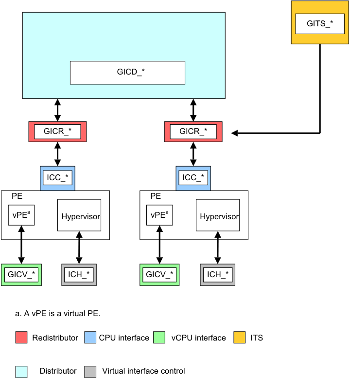
Image text
GITS_
GICD_
GICR_* GICR_
ICC_ ICC_
PE PE
vPE [a] Hypervisor vPE [a] Hypervisor
GICV_ ICH_* GICV_* ICH_*
a. A vPE is a virtual PE.
Redistributor CPU interface vCPU interface ITS
Distributor Virtual interface control
This appendix describes the AXI4-Stream protocol standard message-based interface that the optional GIC Stream Protocol interface uses. It contains the following sections:
-
OverviewA-866 .
-
Signals and the GIC Stream ProtocolA-867 .
-
The GIC Stream ProtocolA-870 .
-
Alphabetic list of command and response packet formatsA-875 . A-865
Appendix A GIC Stream Protocol interface A.1 Overview
A.1 Overview
The GIC Stream Protocol interface describes the optional interface between the IRI and the PE, more specifically that between the Redistributor and the associated CPU interface. The interface supports independent development of an IRI and a PE, that includes System register support for the CPU interface. Arm recommends that a GIC implementation uses this stream protocol interface.
A communication channel that provides a packet interface, based on the AMBA 4 AXI-4 Stream Protocol, is required for each direction:
-
From the Redistributor to the CPU interface.
-
From the CPU interface to the Redistributor.
See Signals and the GIC Stream ProtocolA-867 for more information.
A.1.1 Terminology
The direction of communication for commands is referred to as downstream or upstream, where:
-
Downstream is the direction associated with a command that is initiated by a Redistributor and sent to its associated CPU interface.
-
Upstream is the direction associated with a command initiated by a CPU interface and sent to its associated Redistributor.
Note This terminology can also be applied to communication within an IRI, that is between the Distributor and Redistributor. In this case:
-
An upstream transfer is a transfer from a Redistributor to the Distributor.
-
A downstream transfer is a transfer from the Distributor to a Redistributor. A-866
Appendix A GIC Stream Protocol interface A.2 Signals and the GIC Stream Protocol
A.2 Signals and the GIC Stream Protocol
The GIC Stream Protocol interface is based on the unidirectional AXI4-Stream Interface. Therefore, to support bidirectional communication, the GIC Stream Protocol interface consists of an AXI4-Stream Protocol Interface in each direction, that is:
-
A downstream AXI4-Stream Interface containing connections from one or more Redistributors to an equivalent number of CPU interfaces. On this interface, the Redistributor is the Requester and the CPU interface is the Completer.
-
An upstream AXI4-Stream Interface containing connections from one or more CPU interfaces to an equivalent number of Redistributors. On this interface, the CPU interface is the Requester and the Redistributor is the Completer.
Multiple packets on an AXI4-Stream Interface cannot be interleaved, that is, only one packet can be transferred in each direction at a given time.
Figure A-1 shows an example implementation of the GIC Stream Protocol interface.
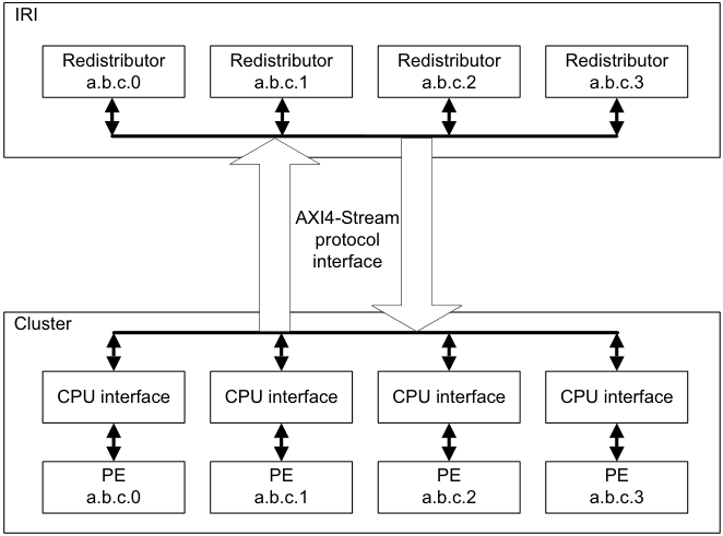
Image text
IRI
Redistributor Redistributor Redistributor Redistributor
a.b.c.0 a.b.c.1 a.b.c.2 a.b.c.3
AXI4-Stream
protocol
interface
Cluster
CPU interface CPU interface CPU interface CPU interface
PE PE PE PE
a.b.c.0 a.b.c.1 a.b.c.2 a.b.c.3
The GIC architecture requires a GIC implementation to include a Redistributor corresponding to each connected CPU interface, and defines an enumeration notation for identifying PEs. On any AXI4-Stream Interface, each Redistributor must only communicate with its corresponding CPU interface.
The AMBA[®] 4 AXI4-Stream Protocol Specification defines a packet as a group of bytes that are transported together across an AXI4-Stream interface.
An interconnect between an IRI and a CPU interface must ensure that the stream packet sequence is transferred over the stream protocol interface in the same order in which it was created.
A.2.1 Signals
The interface requires a global clock, ACLK , and a reset signal, ARESETn .
For the GIC Stream Protocol, each stream interface is identified by a prefix to the AXI-4 signal names:
-
Downstream signals from a Redistributor to the CPU interface are prefixed with the letters IRI .
-
Upstream signals from the CPU interface to a Redistributor are prefixed with the letters ICC . A-867
Appendix A GIC Stream Protocol interface A.2 Signals and the GIC Stream Protocol
Table A-1 shows the GIC Stream Protocol interface from the Redistributor to the downstream CPU interface.
Table A-1 Redistributor to downstream CPU interface
| Signala | Description |
|---|---|
| IRITVALID | When set to 1, this signal indicates that the Requester is driving a valid transfer. |
| IRITREADY | When set to 1, this signal indicates that the Completer can accept a transfer in the current cycle. |
| IRITDATA[BN:0] | The interface data path. |
| IRITLAST | When set to 1, this signal indicates the final transfer of a packet. |
| IRITDEST[N:0] | When more than one PE is supported by the stream interface, this signal identifies the target CPU interface to provide routing information for the stream. Otherwise this signal is not required. |
- a. These signals were previously prefixed with ICD in the preliminary architecture information.
Table A-2 shows the GIC Stream Protocol interface from the CPU interface to the upstream Redistributor.
Table A-2 CPU interface to upstream Redistributor interface
| Signal | Description |
|---|---|
| ICCTVALID | When set to 1, this signal indicates that the Requester is driving a valid transfer. |
| ICCTREADY | When set to 1, this signal indicates that the Completer can accept a transfer in the current cycle. |
| ICCTDATA[BN:0] | The interface data path. |
| ICCTLAST | When set to 1, this signal indicates the final transfer of a packet. |
| ICCTID[N:0] | When more than one PE is supported by the stream interface, this signal identifies the originating CPU interface, to provide routing information for the stream. Otherwise this signal is not required. |
-
In Table A-1 and Table A-2:
-
BN is the number associated with the most significant bit on a datapath that is required to be an integral number of bytes wide.
-
N is the value log(base2) M rounded up to the nearest integer, where M is the number of PEs supported by the interface.
-
Values of TDEST and TID must be allocated sequentially without gaps, in order of ascending affinity.
For further information about the signals used by the GIC Stream Protocol interface, and for details about handshaking, see AMBA[®] 4 AXI4-Stream Protocol Specification .
A.2.2 Packet format
The GIC architecture issues packets across the GIC Stream Protocol interface where the initial half-byte of a packet indicates the packet type.
The declared size of a packet is always a multiple of the implemented datapath width used for the stream transfer. Where the number of bytes required by a packet is less than the overall packet size, the unused bytes are marked as reserved and filled with the value zero. A-868
Appendix A GIC Stream Protocol interface A.2 Signals and the GIC Stream Protocol
Supported INTID sizes
The GIC architecture supports 16-bit and 24-bit INTID fields. Where the INTID is an argument within a packet, the ID length field in the packet header defines which ID format is used, as follows:
-
ID length == 0 for 16-bit INTIDs.
-
ID length == 1 for 24-bit INTIDs.
Note Reserved fields must be transmitted.
A downstream control command is used during interface initialization to inform a CPU interface whether the IRI supports 24-bit INTIDs.
For a 24-bit INTID where bits[23:16] have the value zero, the stream interface is allowed to identify and transfer the packet with a 16-bit INTID field.
A protocol error occurs when a PE generates a packet using a 24-bit INTID with nonzero bits[23:16] and the IRI only supports 16-bit INTIDs.
The Downstream Control Acknowledge command from the CPU interface returns the maximum INTID lengths supported by both the Redistributor and the CPU interface. The Redistributor and the CPU interface must not send a command that contains an INTID exceeding this length.
When both the Redistributor and the CPU interface support an INTID length larger than 16 bits, but the value of an INTID in a particular packet can only be encoded using 16 bits, it is permissible to send a 16-bit value, where ID length == 0b00.
Software generation of protocol errors and packet errors
Software programming must never be permitted to cause a hardware protocol error because this might result in the PE or GIC becoming non-operational.
Where errors exist in the values of fields within packets, this is called a packet error . Protocol and packet errors can cause UNPREDICTABLE behavior. The manner in which these errors are reported is IMPLEMENTATION DEFINED.
Hardware generation of packet errors
If packets are sent that do not correspond to the architected format described in this specification, and the incorrect format is not the result of software misprogramming, then the architecture makes no guarantees about the behavior of the GIC. In such cases, the GIC can become non-operational in many ways, and this might result in the system hanging, data corruption, or any other effect. Physical damage to the system cannot be precluded in some implementations.
In high reliability systems, implementations might choose to report such cases using IMPLEMENTATION DEFINED system errors, but this is outside the scope of the architecture. A-869
Appendix A GIC Stream Protocol interface A.3 The GIC Stream Protocol
A.3 The GIC Stream Protocol
The GIC Stream Protocol supports two types of packet:
-
Command packets for control actions.
-
Response packets that acknowledge command packets.
Note The Activate and Release commands are designated as a command, but also provide a response semantic to the Set and VSet commands. See the Activate and Release commands for more details.
Table A-3 shows a summary of the downstream Redistributor commands.
Table A-3 Redistributor commands
| Parameters in the | Data in | |||
|---|---|---|---|---|
| Command | ID | first 16-bit transfer | subsequent transfers | Description |
| Clear | 0x3 | Bits[7:6]: ID length | INTID | Resets a specified pending physical interrupt. |
| Downstream | 0x8 | Bit[15:12]: Length | Length bytes of | Writes data to the CPU interface. |
| Control | Bits[11:4]: Identifier | data | Length must be greater than 0 and less than 9. | |
| Quiesce | 0x4 | - | - | Requests that the CPU interface enters the quiescent state. |
| Set | 0x1 | Bits[15:8]: Priority Bits[7:6]: ID length Bit[5] GrpMod Bit[4]: Group | INTID | Sets the highest priority pending physical interrupt for a PE. |
| VClear | 0x7 | Bits[7:6]: ID length | Virtual INTID | Resets a specified pending virtual interrupt. This command is provided in GICv4 only. |
| VSet | 0x6 | Bits[15:8]: Priority Bits[7:6]: ID length Bit[4]: Group | Virtual INTID | Sets the highest priority pending virtual interrupt for a VM. This command is provided in GICv4 only. |
Table A-4 shows a summary of the upstream Redistributor responses.
Table A-4 Redistributor responses
| Parameters in the | Data in | |||
|---|---|---|---|---|
| Response | ID | first 16-bit transfer | subsequent transfers | Description |
| Activate | 0xC | Bit[4]: V | - | Acknowledges that the Redistributor received anActivate |
| Acknowledge | command, and confirms that the effects of the activate are visible. | |||
| Arm IHI 0069G |
A-870
Appendix A GIC Stream Protocol interface A.3 The GIC Stream Protocol
Table A-4 Redistributor responses (continued)
| Parameters in the | Data in | |||
|---|---|---|---|---|
| Response | ID | first 16-bit transfer | subsequent transfers | Description |
| Deactivate | 0xA | - | - | Acknowledges that the Redistributor received a |
| Acknowledge | Deactivatecommand, and confirms that the effects of the deactivate are visible. | |||
| Generate SGI | 0x9 | - | - | Acknowledges that the Redistributor received aGenerate |
| Acknowledge | SGIcommand, and that the effects of the command are guaranteed to become visible to other PEs. | |||
| Upstream | 0xB | - | - | Acknowledges receipt of anUpstream Controlcommand, |
| Control | and confirms that the effects of the write operation are | |||
| Acknowledge | visible. |
All other command and response IDs are reserved. If the Redistributor receives a reserved ID, this constitutes a protocol error, see Software generation of protocol errors and packet errorsA-869 .
Table A-5 shows a summary of all the CPU interface commands.
| Table A-5 CPU interface commands | ||||
|---|---|---|---|---|
| Command | ID | Parameters in the first 16-bit transfer | Data in subsequent transfers | Description |
| Activate | 0x1 | Bits[7:6]: ID length Bit[4]: V | INTID | A pending to active notification request as a result of an interrupt acknowledge on the CPU interface. |
| Deactivate | 0x6 | Bits[10:8]: Groups Bits[7:6]: ID length | INTID | Deactivate request for a specified interrupt. |
| Generate SGI | 0x7 | Bits[59:56]: RS Bits[15:12] SGInum Bit[9]: RSV Bit[8]: A3V Bits[7]: IRM Bit[6]: NS Bit[5:4]: SGT | Affinity Routing Values (A0 to A3) | Requests that the Redistributor issues an SGI. |
| Upstream Control | 0x8 | Bits[15:12]: Length Bits[11:4]: Identifier | Length bytes of data | A system control command that might, for example, pass the configuration status to the Redistributor. Length must be greater than 0 and less than 9. |
| A-871 |
Appendix A GIC Stream Protocol interface A.3 The GIC Stream Protocol
Table A-6 shows a summary of all the CPU interface responses.
Table A-6 CPU interface responses
| Parameters in the | Data in | |||
|---|---|---|---|---|
| Response | ID | first 16-bit transfer | subsequent transfers | Description |
| Clear Acknowledge | 0x4 | Bit [4]: V | - | Acknowledges that the CPU interface received aClear command for a specified interrupt. |
| Downstream | 0xB | - | - | Acknowledges that the CPU interface received a |
| Control Acknowledge | Downstream Controlcommand from the Redistributor. | |||
| Quiesce | 0x9 | - | - | Acknowledges aQuiescecommand, and confirms that |
| Acknowledge | the Redistributor to CPU interface is in the quiescent state. | |||
| Release | 0x3 | Bits[7:6] ID length Bit[4]: V | INTID | Releases control of an interrupt when the CPU interface cannot handle the interrupt, and provides a reason for the release. |
All other command and response IDs are reserved. If the CPU interface receives a reserved ID, this constitutes a protocol error, see Software generation of protocol errors and packet errorsA-869 .
A command packet has an equivalent handshake response packet that acknowledges the command. There are two exceptions to this rule:
-
The Clear and VClear commands are both acknowledged by a Clear Acknowledge response with a bitfield in the header that indicates which command is acknowledged.
-
The Set and VSet command packets are acknowledged by a Release response or an Activate command. This means that the Activate command also has the semantics of a response with respect to the Set and VSet commands. When an Activate command is used, the Redistributor acknowledges that command with an Activate Acknowledge response. Release, Activate, and Activate Acknowledge packets all have a bitfield in the header that indicates whether the response is to a Set or VSet command.
-
Responses to a Set or VSet command are dependent on system contexts and events on the CPU interface. A Release response occurs when a pending interrupt that has been forwarded to the CPU interface cannot be maintained as pending or activated by the CPU interface. This can occur, for example, when:
-
The interrupt group of the INTID is disabled.
-
The highest pending physical interrupt is updated by a Set command before it is activated.
-
The highest pending virtual interrupt is updated by a VSet command before it is activated.
-
A.3.1 Rules associated with the downstream Redistributor commands
The following rules affect the generation of Redistributor commands:
-
When GICR_WAKER.ProcessorSleep == 0, the first packet that is issued to the CPU interface must be a Downstream Control packet. This packet communicates the number of supported Security states, together with the physical and virtual INTID lengths that the GIC Stream Protocol interface supports.
-
There can never be more than one outstanding Downstream Control command, and a Redistributor must only generate response packets until the Downstream Control command is acknowledged.
-
On receipt of a Set command, a CPU interface is required to release the previous pending physical interrupt back to the Redistributor.
-
Unless restricted by another rule in this section, two Set commands can be generated and outstanding at the same time, and the Redistributor must be able to accept an Activate command for a physical interrupt when a Set command is transferred. A-872
Appendix A GIC Stream Protocol interface A.3 The GIC Stream Protocol
-
On receipt of a VSet command, a CPU interface is required to release the previous pending virtual interrupt back to the Redistributor.
-
A VSet command must only be generated when the Redistributor is able to accept an Activate command for a virtual interrupt while the VSet command is being transferred.
-
The Redistributor can only issue a single Clear to the CPU interface and must wait for a Clear Acknowledge (with V == 0) before another can be issued. While a Clear is outstanding, no further “Physical Interrupt” packets except acknowledgements can be issued to the CPU interface.
-
The Redistributor can only issue a single VClear to the CPU interface and must wait for a Clear Acknowledge (with V == 1) before another may be issued. While a VClear is outstanding, no further “Virtual Interrupt” packets can be issued to the CPU interface.
-
There can never be more than one outstanding Quiesce command, and a Redistributor must only generate response packets until the Quiesce command is acknowledged with a Quiesce Acknowledge.
-
A Redistributor must not send a VSet or VClear command to a CPU interface that does not support GICv4. The mechanism for determining whether GICv4 is supported is IMPLEMENTATION DEFINED.
-
A VSet and VClear command can specify an INTID:
-
For GICv4.0, in the LPI range.
-
For GICv4.1, in the LPI or SGI range.
-
-
A CPU interface does not send a Deactivate in response to the deactivation of vSGI received in response to a VSet.
A.3.2 Rules associated with the upstream CPU interface commands
The following rules affect the generation of CPU interface commands:
-
There can never be more than one outstanding Upstream Control command, and a CPU interface must wait for an Upstream Control Acknowledge before issuing another Upstream Control command.
-
There can never be more than one outstanding Deactivate command. This means that a CPU interface must wait for a Deactivate command to be acknowledged before issuing another Deactivate command. The CPU interface can continue to send other commands before receiving the Deactivate Acknowledge response.
-
There can never be more than one outstanding Generate SGI command. This means that a CPU interface must wait for a Generate SGI command to be acknowledged before issuing another Generate SGI command. The CPU interface can continue to send other commands before receiving the Generate SGI Acknowledge response.
-
Before issuing a Clear Acknowledge response with the V bit set to 0, the CPU interface must issue any Release commands that are required to move the physical interrupt specified in the Clear command to the inactive state on the CPU interface.
-
Before issuing a Clear Acknowledge response with the V bit set to 1, the CPU interface must issue any Release commands that are required to move the virtual interrupt specified in the VClear command to the inactive state on the CPU interface.
-
Before issuing a Quiesce Acknowledge response, all other outstanding commands from the Redistributor must be acknowledged, and a Release command must remove any pending interrupts on the CPU interface.
-
A CPU interface always responds to Set commands in the order SETs are received.
-
A CPU interface always responds to Virtual Set (VSet) commands in the order VSet commands are received.
-
A Release command with V==1 can specify an INTID:
- For GICv4.0 in the LPI range.
-
For GICv4.1 in the LPI or SGI range. A-873
Appendix A GIC Stream Protocol interface A.3 The GIC Stream Protocol
- For a Clear, or VClear, with INTID=1023, the CPU interface responds with an acknowledge, but otherwise ignores the command.
Priority-based routing
When ICC_CTLR_EL3.PMHE == 0, or ICC_CTLR_EL1.PMHE == 0:
- The CPU interface must not issue a Release command for a pending SPI because the priority of the SPI is equal to or less than that indicated by ICC_PMR_EL1.
Note The CPU interface might still issue a Release command for a pending SPI for other reasons, such as the SPI belonging to a group that is disabled in the CPU interface, or in response to receipt of a Clear command from the IRI.
When ICC_CTLR_EL3.PMHE == 1 or ICC_CTLR_EL1.PMHE == 1:
-
The CPU interface must issue an Upstream Control command, with the identifier 0x02, when the PE successfully writes to ICC_PMR_EL1:
- If multiple writes to ICC_PMR_EL1 occur before the CPU interface issues the Upstream Control command, the GIC can combine these writes into a single command.
-
The CPU interface can issue a Release command for a pending SPI with a priority that is equal to or less than the value in ICC_PMR_EL1, if the Set command was received between the architectural execution of the instruction that updated ICC_PMR_EL1 and the receipt of the Upstream Control Acknowledge command that indicates that the new ICC_PMR_EL1 value has been observed. Whether a Release is generated in this situation is IMPLEMENTATION DEFINED.
-
The CPU interface must not issue a Release command for a pending SPI with a priority that is greater than the value in ICC_PMR_EL1 if the Set command was not received between the architectural execution of the instruction that updated ICC_PMR_EL1 and the receipt of the Upstream Control Acknowledge that indicates that the new ICC_PMR_EL1 value has been observed.
Note The CPU interface might still issue a Release command for a pending SPI for other reasons, such as the SPI belonging to a group that is disabled in the CPU interface or in response to receipt of a Clear command from the IRI. A-874
Appendix A GIC Stream Protocol interface A.4 Alphabetic list of command and response packet formats
A.4 Alphabetic list of command and response packet formats
This subsection lists all the command and response packet formats in alphabetical order. The heading for each command or response subsection includes a label, ICC or IRI, that indicates the agent that generated the packet. A-875
Appendix A GIC Stream Protocol interface A.4 Alphabetic list of command and response packet formats
A.4.1 Activate (ICC)
The CPU interface sends an Activate command when acknowledging an interrupt. When the Redistributor receives the Activate command, it sets the interrupt to the active state. The CPU interface must send an Activate command only when Redistributor action is required, as follows:
-
For SPIs, SGIs, and PPIs, where the Redistributor must clear the pending bit for edge-triggered interrupts, and set the active bit.
-
For LPIs where the Redistributor must clear the pending bit.
The Activate command generated by the CPU interface, unlike other commands, also acts as a response to a Set or VSet command:
- A Set or VSet command results in a Release response or Activate command in finite time. The amount of time is determined by when the pending interrupt changes its state within the CPU interface. An Activate command acknowledges the original Set command. The Activate command is itself acknowledged using an Activate Acknowledge response from the Redistributor.
Figure A-2 shows the Activate command format.
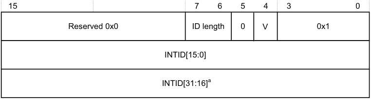
15 7 6 5 4 3 0
Reserved 0x0 ID length 0 V 0x1
INTID[15:0]
INTID[31:16] [a]
- a. If the command includes this field, bits[31:24] are 0.
Figure A-2 Activate
In Figure A-2:
-
ID length indicates the number of INTID bits the Activate command includes. See Supported INTID sizesA-869 for more information.
-
V indicates the original command to which the Activate command corresponds:
-
0 The Activate corresponds to a Set command.
-
1 The Activate corresponds to a VSet command.
-
-
INTID is the value that the CPU interface returns after a valid read of ICC_IAR0_EL1, ICC_IAR1_EL1, or GICC_IAR.
Note
During legacy operation, the INTID that is returned for SGIs includes the source PE in the GICC_IAR.Source_CPU_ID field.
A.4.2 Activate Acknowledge (IRI)
The Redistributor sends an Activate Acknowledge response to confirm receipt of an Activate command, and confirms that the effects of the activate operation are visible to the Redistributor and other PEs. Figure A-3A-877 shows the Activate Acknowledge response format. A-876
Appendix A GIC Stream Protocol interface A.4 Alphabetic list of command and response packet formats
| 15 | 4 5 | 4 5 | 3 0 | |
|---|---|---|---|---|
| Reserved 0x0 | V | 0xC |
Figure A-3 Activate Acknowledge
In Figure A-3, V indicates the original command to which the Activate Acknowledge corresponds: 0b0 The Activate Acknowledge corresponds to a Set command. 0b1 The Activate Acknowledge corresponds to a VSet command.
Note There is no requirement for ActivateAcknowledge commands to be issued in the same order as the Activate command to which they are responding. A-877
Appendix A GIC Stream Protocol interface A.4 Alphabetic list of command and response packet formats
A.4.3 Clear (IRI)
The Clear command clears the specified pending interrupt. Figure A-4 shows the Clear command format.
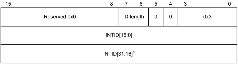
15 8 7 6 5 4 3 0
Reserved 0x0 ID length 0 0 0x3
INTID[15:0]
INTID[31:16] [a]
a. If the command includes this field, bits[31:24] are 0.
Figure A-4 Clear
In Figure A-4:
-
ID length indicates the number of INTID bits that the Clear command includes. See Supported INTID sizesA-869 for more information.
-
INTID identifies the interrupt to be cleared.
The CPU interface must always respond to a Clear command with a Clear Acknowledge response where V == 0.
If the interrupt is pending in the CPU interface, the CPU interface must issue a Release response, or an Activate response that remains outstanding for the interrupt before it issues a Clear Acknowledge command.
If the interrupt is not pending or present on the CPU interface, the Clear command has no effect. However, the CPU interface must still issue a Clear Acknowledge response.
Note A Clear command with INTID = 1023 has no effect, but a Clear Acknowledge response must still be generated.
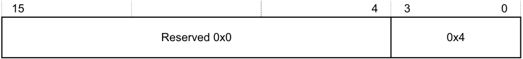
A.4.4 Clear Acknowledge (ICC)
The CPU interface sends a Clear Acknowledge response to acknowledge the receipt of a Clear or VClear command. Figure A-5 shows the Clear Acknowledge response format.

15 8 7 6 5 4 3 0
Reserved 0x0 0 0 0 V 0x4
Figure A-5 Clear Acknowledge
In Figure A-5, V indicates the original command to which the Clear Acknowledge corresponds:
0 The Clear Acknowledge corresponds to a Clear command. 1 The Clear Acknowledge corresponds to a VClear command.
Note No INTID field is required for this command because only a single Clear can be outstanding for a CPU interface at any time. A-878
Appendix A GIC Stream Protocol interface A.4 Alphabetic list of command and response packet formats
A.4.5 Deactivate (ICC)
The Deactivate command deactivates an interrupt, provided the initiating Exception level and Security state can access the interrupt group to which the INTID belongs. The Redistributor sends a Deactivate Acknowledge in response to a Deactivate command. Figure A-6 shows the Deactivate command format.
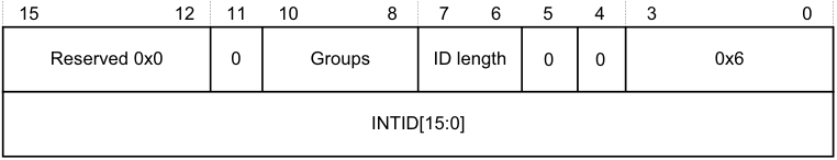
15 12 11 10 8 7 6 5 4 3 0
Reserved 0x0 0 Groups ID length 0 0 0x6
INTID[15:0]
Figure A-6 Deactivate
In Figure A-6:
-
Groups indicates the interrupt groups that the initiating Exception level and Security state are permitted to modify:
-
Bit[10] When this bit is set to 1, Secure Group 1 interrupts can be modified.
-
Bit[9] When this bit is set to 1, Non-secure Group 1 interrupts can be modified. Bit[8] When this bit is set to 1, Group 0 interrupts can be modified.
-
Note When sending a Deactivate command, at least one of the Groups bits must be set to 1. A protocol error occurs if none of these bits are set to 1.
-
ID length indicates the number of INTID bits the Deactivate command includes. See Supported INTID sizesA-869 for more information. The Deactivate command applies only to SPIs, PPIs, and SGIs, each of which has INTIDs no higher than 8192. This field must therefore be set to 0b00, indicating a 16-bit INTID.
-
INTID is the 32-bit value read from the corresponding interrupt acknowledge cycle that is presented in the write to ICC_EOIR0_EL1 or ICC_EOIR1_EL1.
Note There is no requirement for the CPU interface to have received the corresponding Activate Acknowledge command before sending the Deactivate command.
When System register access is enabled for the initiating Exception level and Security state, one of the Groups bits is set according to the rules in Groups field when System register access is enabledA-880 .
Note In an implementation that supports two Security states, for Secure EL1 to be permitted to handle Group 1 interrupts, that is, IRQs not taken to EL3, both bit[9] and bit[10] must be set to 1.
When System register access is not enabled for the initiating Exception level and Security state, the Groups field is set according to the Security state of the initiating Exception level. That is, bit [9] is set to 1 for Non-secure write access, and bits [10:8] are all set to 1 for Secure write access. In an implementation that supports only a single Security state, write accesses that result in the generation of a Deactivate command are treated as Secure writes.
In an implementation that supports two Security states, Group 0 and Secure Group 1 interrupts can be modified only from a Secure initiating Exception level. This includes EL3, regardless of the setting of SCR_EL3.NS. In an implementation that supports only a single Security state, the Redistributor can ignore bit[10]. A-879
Appendix A GIC Stream Protocol interface A.4 Alphabetic list of command and response packet formats
Note The Redistributor must send a Deactivate Acknowledge in response to a Deactivate command.
-
If affinity routing is enabled for an interrupt group, the Redistributor must acknowledge, but otherwise ignore, any Deactivate command with an ID in the range 1019 < INTID < 8192.
-
If affinity routing is not enabled for an interrupt group, the Redistributor must acknowledge, but otherwise ignore any Deactivate command with an ID in the range 1019 < INTID < 8192 where bits [9:4] are not 0. That is, it might issue Deactivate packets for SGIs with a non-zero CPU number in bits[12:10] of GICC_IAR.
-
If affinity routing is not enabled for an interrupt group and the ID specifies an SGI, and the PE specified by the CPU number in bits[12:10] does not support operation when affinity routing is not enabled, the Redistributor must acknowledge but otherwise ignore the Deactivate command.
Groups field when System register access is enabled
When System register access is enabled for the initiating Exception level and Security state, the following pseudocode describes the rules for specifying the value of the Groups field:
// This invalidates any caches containing the configuration data
for all interrupts in the
// collection. Over invalidation is permitted.
InvalidateCollectionCaches(UInt(cmd.ICID));
IncrementReadPointer();
return;
A.4.6 Deactivate Acknowledge (IRI)
The Redistributor sends a Deactivate Acknowledge response to confirm receipt of a Deactivate command, and to confirm that the effects of the deactivate operation are visible to the Redistributor and other PEs. Figure A-7 shows the Deactivate Acknowledge response format.
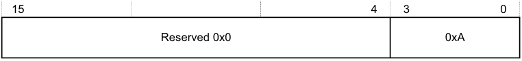
15 4 3 0
Reserved 0x0 0xA
Figure A-7 Deactivate Acknowledge
A.4.7 Downstream Control (IRI)
The Downstream Control command transfers a specified number of bytes of data to the CPU interface. Figure A-8 shows the Downstream Control command format.
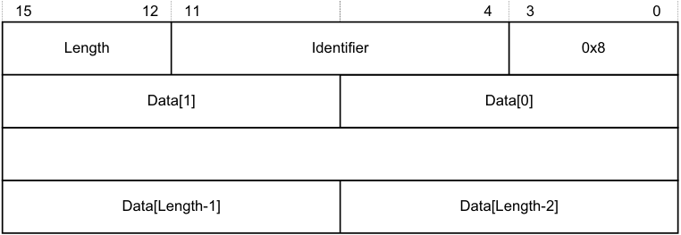
15 12 11 4 3 0
Length Identifier 0x8
Data[1] Data[0]
Data[Length-1] Data[Length-2]
Figure A-8 Downstream Control
In Figure A-8:
-
Length indicates the number of bytes of valid data appended to the 2 byte header.
- If this field specifies a number of bytes that is not exactly divisible by the interface width, as Signals and the GIC Stream ProtocolA-867 describes, any surplus bytes beyond this specified length in the last transfer must be zero. The CPU interface must ignore such bytes. A-881
Appendix A GIC Stream Protocol interface A.4 Alphabetic list of command and response packet formats
- Identifier is a value that specifies the format of the data provided, and can have the values shown in Table A-7.
Table A-7 Downstream Control Identifier values
| Data value name Identifier value Length | Data value name Identifier value Length | Data value name Identifier value Length | Contents |
|---|---|---|---|
| Settings (configure interface) 0x00 0x1 | Data[0] holds the Redistributor global settings, and these bits have the following meanings: [7:6] VL. Indicates the supported vINTID length. [5:4] PL. Indicates the supported pINTID length. [3:2] Reserved. RES0. [1] RSS. Indicates the value ofGICD_TYPER.RSS. [0] DS. Disable Security. Indicates the value ofGICD_CTLR.DS. Note Bit[0] is set to 1 if the GIC supports only a single Security state. | ||
| Reserved 0x01-0x7F - | - | ||
| IMPLEMENTATION DEFINED 0x80-0xFF - | Reserved forIMPLEMENTATION DEFINEDvariables. | ||
| Note | |||
| Each identifier length. | value can have | a different length, but a particular identifier value must always have the same |
The CPU interface must always respond to a Downstream Control command with a Downstream Control Acknowledge response.
After the CPU interface receives a Downstream Control command where DS == 1, a packet protocol violation occurs if it receives a subsequent Downstream Control command where DS == 0, before an intervening hardware reset.
If a CPU interface receives an IMPLEMENTATION DEFINED value that it cannot interpret, this constitutes a protocol error. See Software generation of protocol errors and packet errorsA-869 .
Note The IMPLEMENTATION DEFINED values of the Downstream Write Command must only be used where the Distributor and the CPU interface interpret the IMPLEMENTATION DEFINED values to mean the same thing. This is typically the case where both components have been produced as part of the same system design.
A.4.8 Downstream Control Acknowledge (ICC)
The CPU interface sends a Downstream Control Acknowledge response to confirm receipt of a Downstream Control command. Figure A-9 shows the Downstream Control Acknowledge response format.
| 15 | 8 | 4 7 6 5 | 4 7 6 5 | 3 0 |
|---|---|---|---|---|
| Reserved 0x0 | VL | PL | 0xB |
Figure A-9 Downstream Control Acknowledge
In Figure A-9:
- VL indicates the virtual INTID length, that is, the supported number of INTID bits. A-882
Appendix A GIC Stream Protocol interface A.4 Alphabetic list of command and response packet formats
- PL indicates the physical INTID length, that is, the supported number of INTID bits.
See Supported INTID sizesA-869 for more information.
VL must be set to the minimum of:
-
The value of VL contained in the first Downstream Control command received after reset.
-
The value that ICH_VTR_EL2.IDbits specifies.
PL must be set to the minimum of:
-
The value of PL contained in the first Downstream Control command received after reset.
-
The value that ICC_CTLR_EL3.IDbits or ICC_CTLR_EL1.IDbits, as appropriate, specifies.
A.4.9 Generate SGI (ICC)
The CPU interface sends a Generate SGI command to the Redistributor to generate an SGI. The Redistributor sends a Generate SGI Acknowledge in response to a Generate SGI command. Figure A-10 shows the Generate SGI command format.
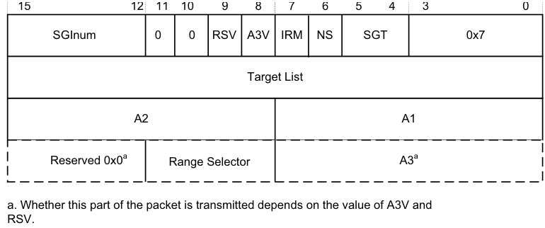
Image text
15 12 11 10 9 8 7 6 5 4 3 0
SGInum 0 0 RSV A3V IRM NS SGT 0x7
Target List
A2 A1
Reserved 0x0 [a] Range Selector A3 [a]
a. Whether this part of the packet is transmitted depends on the value of A3V and
RSV.
-
SGInum indicates the INTID of the SGI to be generated.
-
RSV (Range Selector Valid) indicates whether the RS field is valid:
-
0 RS is RES0.
-
1 RS indicates the affinities covered by Target List.
-
-
A3V indicates whether the command includes an A3 field. When A3V is 0, the packet does not include an A3 field, and the Redistributor must use 0 as the value of A3.When a CPU interface supports the Aff3 field and a write to ICC_SGI0R, ICC_SGI1R or ICC_ASGI1R specifies Aff3 == 0, the resulting packet must clear A3V to zero.
-
IRM indicates the Interrupt Routing Mode to be used. When IRM is set to 1, Target List, A1, A2, and A3 are ignored. The A3V field is RES0.
-
NS indicates whether the Generate SGI command originates from Non-secure state: 0 The command originates from a Secure Execution state. 1 The command originates from a Non-secure Execution state.
-
SGT specifies the register access that caused the Generate SGI command: 0b00 ICC_SGI0R_EL1. 0b01 ICC_SGI1R_EL1. 0b10 ICC_ASGI1R_EL1. 0b11 Reserved. A-883
Appendix A GIC Stream Protocol interface A.4 Alphabetic list of command and response packet formats
When the Redistributor supports two Security states and affinity routing is not enabled for the Secure state in the Redistributor, Generate SGI commands that correspond to Non-secure writes to ICC_SGI0R_EL1 and ICC_ASGI1R_EL1 must be acknowledged and discarded, and must not set an SGI pending.
When the Redistributor supports a single Security state, that is, GICD_CTLR.DS == 1, Generate SGI commands that correspond to Non-secure writes to ICC_SGI0R_EL1 or ICC_ASGI1R_EL1 generate a Group 0 SGI.
-
Target List is the group of target PEs defined by the routing mode. For SGIs, the GIC routing mode defines a group of target PEs, targetlist. This field is treated as defined in ICC_SGI0R_EL1, ICC_SGI1R_EL1, and ICC_ASGI1R_EL1.
-
A1, A2, and A3 are the affinity level values used for generating the set of target PEs. These fields are treated in the same way as the Affinity value fields in ICC_SGI0R_EL1, ICC_SGI1R_EL1, and ICC_ASGI1R_EL1 Whether the A3 field is supported is IMPLEMENTATION DEFINED.
Note In systems where the Redistributor only supports the zero value for A3, the Redistributor must acknowledge any Generate SGI commands where A3V == 1 with a Generate SGI Acknowledge response, but must otherwise ignore the command.
- RS (Range Selector) indicates the affinities covered by Target List. This field is treated as defined in ICC_SGI0R_EL1, ICC_SGI1R_EL1, and ICC_ASGI1R_EL1.
A.4.10 Generate SGI Acknowledge (IRI)
The Redistributor sends a Generate SGI Acknowledge response to confirm that it has received a Generate SGI command from the CPU interface, and that the effects of that command are guaranteed to become visible to other PEs. Figure A-11 shows the Generate SGI Acknowledge response format.

15 4 3 0
Reserved 0x0 0x9
Figure A-11 Generate SGI Acknowledge
Note Receipt of a Generate SGI Acknowledge response by a CPU interface does not guarantee that the corresponding SGI pending state is set, but it does guarantee that the pending state will become set.
A.4.11 Quiesce (IRI)
The Redistributor sends a Quiesce command to request that the CPU interface enters the quiescent state. Figure A-12 shows the Quiesce command format.
15 4 3 0
Reserved 0x0 0x4
Figure A-12 Quiesce
A CPU interface is quiescent when there are no pending interrupts and all outstanding operations are complete. To ensure quiescence, a CPU interface must:
-
Respond to any outstanding Clear and VClear commands by sending a Clear Acknowledge command.
-
Release any pending virtual or physical interrupts.
-
Ensure it receives an acknowledge response from the Redistributor to indicate completion of all outstanding:
- Generate SGI requests. A-884
Appendix A GIC Stream Protocol interface A.4 Alphabetic list of command and response packet formats
  - Activate requests.

  - Deactivate requests.
-
Upstream Control.
-
Respond to the Quiesce commands by sending a Quiesce Acknowledge response as the final transfer.
In addition, software must ensure that the Redistributor receives no traffic after the CPU interface sends the Quiesce Acknowledge response. Failure to adhere to this result in UNPREDICTABLE behavior. In practice, because such timing is not predictable, software must ensure that no traffic is generated after the GICR_WAKER.ProcessorSleep bit is set to 1, see Chapter 11 Power Management .
A CPU interface cannot receive a Quiesce command if a Downstream Control Acknowledge response is outstanding. See Rules associated with the downstream Redistributor commandsA-872 for more information.
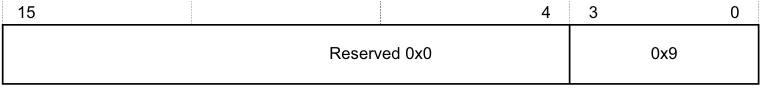
A.4.12 Quiesce Acknowledge (ICC)
The CPU interface sends a Quiesce Acknowledge response to confirm receipt of a Quiesce command, and to confirm that it is quiescent. Figure A-13 shows the Quiesce Acknowledge response format.
15 4 3 0
Reserved 0x0 0x9
Figure A-13 Quiesce Acknowledge
The Quiesce command acts as a form of barrier. Before sending a Quiesce Acknowledge response, the CPU interface must be quiescent, that is, it must fulfil the requirements for quiescence specified in Quiesce (IRI)A-884 .
A.4.13 Release (ICC)
The CPU interface logic sends a Release response when it cannot handle a particular interrupt. Figure A-14 shows the Release response format.

15 8 7 6 5 4 3 0
Reserved 0x0 ID length 0 V 0x3
INTID[15:0]
INTID[31:16] [a]
- a. If the command includes this field, bits[31:24] are 0.
Figure A-14 Release
In Figure A-14:
-
ID length indicates the number of INTID bits the Release response includes. See Supported INTID sizesA-869 for more information.
-
V indicates the original command to which the Release response corresponds:
- 0 The Release corresponds to a Set command. 1 The Release corresponds to a VSet command.
-
INTID is the value that the CPU interface returns after a valid read of ICC_IAR0_EL1 or ICC_IAR1_EL1. A-885
Appendix A GIC Stream Protocol interface A.4 Alphabetic list of command and response packet formats
Note
-
During legacy operation, the INTID that is returned for SGIs includes the source PE in the GICC_IAR.Source_CPU_ID field.
-
If the INTID corresponds to an interrupt that uses the 1 of N model, the Redistributor might forward the interrupt to a different PE or it might send the interrupt to the same PE again. See Priority-based routingA-874 for information about how the PMHE field might affect the 1 of N selection.
If the CPU interface issues a Release response as a result of disabling an interrupt group, Arm recommends that it sends the Upstream Control command that contains the revised interrupt group enable information before issuing the Release response.
A.4.14 Set (IRI)
The Set command sets the highest priority pending interrupt for a PE. The PE has control of the interrupt and might respond to a read of ICC_IAR0_EL1 or ICC_IAR1_EL1 with the INTID. Figure A-15 shows the Set command format.
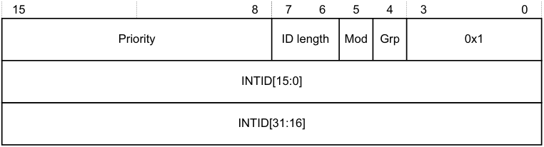
15 8 7 6 5 4 3 0
Priority ID length Mod Grp 0x1
INTID[15:0]
INTID[31:16]
Figure A-15 Set
In Figure A-15:
-
Priority indicates the actual priority of the interrupt, that is, the Secure, unshifted view. Bits corresponding to unimplemented priority bits in the CPU interface are RES0.
-
ID length indicates the number of INTID bits the Set command includes. See Supported INTID sizesA-869 for more information.
-
Mod represents the value of the GICD_IGRPMODR
.Group status bit for the interrupt. -
Grp represents the interrupt group, as indicated by the corresponding GICD_IGROUPR
.Group status bit. -
INTID is the value that the CPU interface returns after a valid read of an ICC_IAR0_EL1 or ICC_IAR1_EL1.
- **Note**- During legacy operation, the INTID that is returned for SGIs includes the source PE in the GICC_IAR.Source_CPU_ID field.
If the Redistributor sends a Set command, the interrupt specified in the command replaces any outstanding highest pending interrupt, that is, the command sets a new highest priority pending interrupt. Where a pending interrupt is replaced, the CPU interface must Release it back to the Redistributor.
The Redistributor must:
-
Ensure that no more than two Set commands that are waiting for a response are outstanding per PE at any time.
-
Send a Set command only if it can accept an Activate command where V == 0.
- Note
An implementation can guarantee this by treating the Set command as outstanding until either a Release command is received for the Set command, or an Activate Acknowledge response is sent for the corresponding Activate. A-886
Appendix A GIC Stream Protocol interface A.4 Alphabetic list of command and response packet formats
-
Never send a Set command when any of the following conditions apply:
-
The INTID is a special interrupt number, that is, 1020-1023.
-
Affinity routing is enabled for an interrupt group and the INTID value is invalid.
-
-
Affinity routing is not enabled for an interrupt group, 1023 < INTID < 8192, and bits[9:4] are non-zero. That is, the Redistributor is permitted to send Set commands for SGIs where bits[12:10] of ICC_IAR0_EL1 or ICC_IAR1_EL1 specify the CPUID of the source PE.
-
Affinity routing is not enabled for an interrupt group, and INTID > 8191
-
The Set command has the same INTID as a previous Set command, unless the Redistributor has received an Activate command or Release response.
The Redistributor must not send a SET command for an interrupt until all of the following are true:
-
All previous outstanding SET commands for that interrupt have been returned through a Release or Activate command.
-
The interrupt is in the pending state, see Interrupt handling state machine .
If the interrupt group is disabled, the CPU interface cannot handle the interrupt, and must Release the interrupt.
A.4.15 Upstream Control (ICC)
This command communicates data to the Redistributor. Figure A-16 shows the Upstream Control command format.
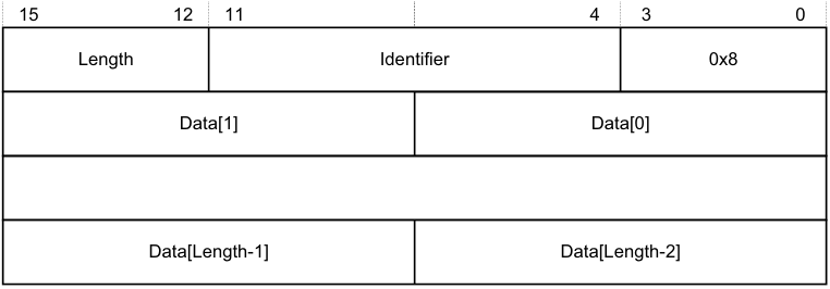
15 12 11 4 3 0
Length Identifier 0x8
Data[1] Data[0]
Data[Length-1] Data[Length-2]
Figure A-16 Upstream Control
In Figure A-16:
-
Length indicates the number of bytes of valid data.
- If this field specifies a number of bytes that is not exactly divisible by the interface width, as Signals and the GIC Stream ProtocolA-867 describes, any surplus bytes beyond this specified length in the last transfer must be zero. The Redistributor must ignore such bytes.
-
Identifier is a value that specifies the format of the data provided. A-887
Appendix A GIC Stream Protocol interface A.4 Alphabetic list of command and response packet formats
Table A-8 shows the possible Identifier values.
| Table A-8 Upstream Control Identifier values | |
|---|---|
| Data value Identifier Length | Contents of Data[0] field |
| Physical interface enables 0x00 0x1 | This value contains the physical CPU interface enable bit values that must be communicated to the Redistributor. Bits [2:0] of Data[0] have the following meanings: [2] EnableGrp1, secure. The value of the Secure copy of ICC_IGRPEN1_EL1.Enable. [1] EnableGrp1, Non-secure. The value of the Non-secure copy of ICC_IGRPEN1_EL1.Enable. [0] EnableGrp0, Secure. The value ofICC_IGRPEN0_EL1.Enable. When GICD_CTLR.DS==1: • EnableGrp1, Secureis always reported as disabled. When GICD_CTLR.DS==0 and the PE supports a single Security state: • PE is always Secure: — EnableGrp1, Non-secureis always reported as disabled. • PE is always Non-secure: — EnableGrp0, Secureis always reported as disabled. — EnableGrp1, Secureis always reported as disabled. To ensure the state of the enable bits can be communicated easily to the Redistributor after powerup, this command must be generated by any write to a physical enable bit. If multiple writes to a physical enable bit occur before the CPU interface issues the command, the GIC can combine these writes into a single command. |
| Virtual interface enables 0x01 0x1 | This value contains the virtual CPU interface enable bit values that must be communicated to the Redistributor. Bits [1:0] of Data[0] have the following meanings: [1] EnableGrp1. The value ofICH_VMCR_EL2.VENG1. [0] EnableGrp0. The value ofICH_VMCR_EL2.VENG0. To ensure the state of the enable bits can be communicated easily to the Redistributor after powerup, this command must be generated by any write to a virtual enable bit. If multiple writes to a virtual enable bit occur before the CPU interface issues the command, the GIC can combine these writes into a single command. Only a CPU interface that supports GICv4 can generate this identifier. Note If EL2 accesses memory-mapped registers, and usesGICH_VMCR, the VM must access GICV_* registers. If the GIC shares state between the GICH_* registers and the ICH_* System registers, it might communicate any change to the virtual enable bits. |
| A-888 |
Appendix A GIC Stream Protocol interface A.4 Alphabetic list of command and response packet formats
Table A-8 Upstream Control Identifier values (continued)
| Data value Identifier Length | Contents of Data[0] field |
|---|---|
| Physical priority 0x02 0x1 | This value contains the current value of the Priority Mask Register (PMR): [7:0] The value written toICC_PMR_EL1. The CPU interface must issue this command when the PE successfully writes to ICC_PMR_EL1andICC_CTLR_EL3.PMHE bit is set to 1. The command must be generated by any successful write that changes the value of ICC_PMR_EL1. If multiple writes toICC_PMR_EL1occur before the CPU interface issues the command, the GIC can combine these writes into a single command. Note • In GIC implementations that use this value, the Redistributor copy of the value must reset to the idle priority, that is,0xF8in cases where only 5 bits of priority are implemented. • If the CPU interface receives aSetcommand with a priority lower than the current value inICC_PMR_EL1before theUpstream Control Acknowledgeis received, the GIC mightReleasethatSetcommand. |
| - 0x03 - 0x07 - | Reserved. |
| - 0x80 - 0xFF - | IMPLEMENTATION DEFINED |
If a Redistributor receives an IMPLEMENTATION DEFINED value that it cannot interpret, this constitutes a protocol error. See Software generation of protocol errors and packet errorsA-869 .
A.4.16 Upstream Control Acknowledge (IRI)
The Redistributor sends an Upstream Control Acknowledge response to confirm receipt of an Upstream Control command, and to confirm that the effects of the write operation are visible to the Distributor. Figure A-17 shows the Upstream Control Acknowledge response format.
| 15 | 4 | 3 0 |
|---|---|---|
| Reserved 0x0 | 0xB |
Figure A-17 Upstream Control Acknowledge
A-889
Appendix A GIC Stream Protocol interface A.4 Alphabetic list of command and response packet formats
A.4.17 VClear (IRI)
The VClear command resets the highest priority pending virtual interrupt.
This command is provided in GICv4 only.
Figure A-18 shows the VClear command format.

15 8 7 6 5 4 3 0
Reserved 0x0 ID length 0 0 0x7
vINTID[15:0]
vINTID[31:16] [a]
- a. If the command includes this field, bits[31:24] are 0.
Figure A-18 VClear
In Figure A-18:
-
ID length indicates the number of vINTID bits the VClear command includes. See Supported INTID sizesA-869 for more information.
-
vINTID identifies the virtual interrupt to be cleared.
The CPU interface must always respond to a VClear command by sending a Clear Acknowledge response where V==1.
If the interrupt is pending in the CPU interface, the CPU interface must issue a Release response, or an Activate response that remains outstanding for the interrupt before it issues a Clear Acknowledge command.
If the interrupt is not pending or present on the CPU interface, the VClear command has no effect. However, the CPU interface must still issue a Clear Acknowledge response.
Note This command does not affect LPIs in the List registers.
A.4.18 VSet (IRI)
The Redistributor sends a VSet command to set a virtual interrupt pending for a VM. The PE has control of the interrupt and can respond to a read of ICC_IAR0_EL1 or ICC_IAR1_EL1 with the vINTID.
This command is provided in GICv4 only.
Figure A-19A-891 shows the VSet command format. A-890
Appendix A GIC Stream Protocol interface A.4 Alphabetic list of command and response packet formats
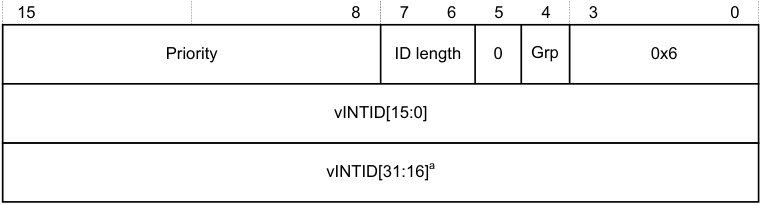
15 8 7 6 5 4 3 0
Priority ID length 0 Grp 0x6
vINTID[15:0]
vINTID[31:16] [a]
- a. If the command includes this field, bits[31:24] are 0.
Figure A-19 VSet
In Figure A-19:
-
Priority indicates the actual priority of the interrupt, that is, the Secure, unshifted view. Bits corresponding to unimplemented priority bits in the CPU interface are RES0.
-
ID length indicates the number of v INTID bits the VSet command includes. See Supported INTID sizesA-869 for more information.
-
Grp represents the interrupt group.
-
vINTID is the value that the CPU interface returns after a valid read of ICC_IAR0_EL1 or ICC_IAR1_EL1. When affinity routing is not enabled for a Security state, the CPUID field in ICC_IAR0_EL1 and ICC_IAR1_EL1 identifies the source PE for SGIs.
The Redistributor sends a VSet command when the virtual interrupt specified by vINTID is set as pending in the resident virtual LPI Pending table. The CPU interface must either activate the virtual interrupt by sending an Activate command where V == 1, or Release the virtual interrupt to the Redistributor.
If the Redistributor sends a VSet command, the interrupt specified in the command always replaces any previous interrupt, that is, the command sets a new highest priority pending interrupt. If the replaced interrupt is still valid and pending, the CPU interface must Release it back to the Redistributor.
The Distributor must:
-
Ensure no more than two VSet commands that are waiting for a response are outstanding per PE at any time.
-
Send a VSet command only if it can accept an Activate command where V == 1.
Note An implementation can guarantee this by treating the VSet command as outstanding until either a Release response is received for the VSet command, or an Activate Acknowledge response is sent for the corresponding Activate command.
-
Never send a VSet command when Virtual INTID < 8192. However, in GICv4.1, VSET and VCLEAR commands can specify an INTID in the SGI ranges as well.
-
Send a VSet command for an interrupt after receipt of either an Activate or a Release command for that particular interrupt.
The CPU interface must Release an interrupt, ensuring that V == 1, if it cannot handle the interrupt for either of the following reasons:
-
The interrupt group is disabled. This includes when the VM interface is disabled, that is, when GICH_HCR.En or ICH_HCR.En, as appropriate, is cleared to 0.
-
The hypervisor is not using the System register interface, that is, when either of the following applies: — During legacy operation, when ICC_SRE_EL2.SRE == 0.
- EL2 is not present.
When the Non-secure copy of ICC_SRE_EL1.SRE == 0, it is UNPREDICTABLE whether the specified virtual interrupt is factored into virtual priority calculations and reads of the GICV_* registers. A-891
Appendix A GIC Stream Protocol interface A.4 Alphabetic list of command and response packet formats A-892
Appendix B Pseudocode Definition
This appendix provides a definition of the pseudocode used in this specification, and lists the helper procedures and support functions used by pseudocode to perform useful architecture-specific jobs. For functions that are referenced in this specification but that are not defined in this appendix, see Arm[®] Architecture Reference Manual, Armv8, for Armv8-A architecture profile .
This appendix contains the following sections:
-
_About Arm pseudocode_B-894.
-
_Data types_B-895.
-
_Expressions_B-899.
-
_Operators and built-in functions_B-901.
-
_Statements and program structure_B-906.
-
_Pseudocode terminology_B-910.
-
_Miscellaneous helper procedures and support functions_B-911. B-893
Appendix B Pseudocode Definition B.1 About Arm pseudocode
B.1 About Arm pseudocode
Arm pseudocode provides precise descriptions of some areas of the architecture. The following sections describe the pseudocode in detail:
-
_Data types_B-895.
-
_Expressions_B-899.
-
_Operators and built-in functions_B-901.
-
_Statements and program structure_B-906.
_Miscellaneous helper procedures and support functions_B-911 describes some pseudocode helper functions that are used by the pseudocode functions that are described elsewhere in this document.
B.1.1 General limitations of Arm pseudocode
The pseudocode statements IMPLEMENTATION_DEFINED, SEE, UNDEFINED, and UNPREDICTABLE indicate behavior that differs from that indicated by the pseudocode being executed. If one of these statements is encountered:
-
Earlier behavior indicated by the pseudocode is only specified as occurring to the extent required to determine that the statement is executed.
-
No subsequent behavior indicated by the pseudocode occurs. This means that these statements terminate pseudocode execution.
For more information, see _Simple statements_B-906. B-894
Appendix B Pseudocode Definition B.2 Data types
B.2 Data types
This section describes:
-
General data type rules .
-
Bitstrings .
-
_Integers_B-896.
-
_Reals_B-896.
-
_Booleans_B-896.
-
_Enumerations_B-896.
-
_Lists_B-897.
-
_Arrays_B-898.
B.2.1 General data type rules
Arm architecture pseudocode is a strongly-typed language. Every constant and variable is of one of the following types:
-
Bitstring.
-
Integer.
-
Boolean.
-
Real.
-
Enumeration.
-
List.
-
Array.
The type of a constant is determined by its syntax. The type of a variable is normally determined by assignment to the variable, with the variable being implicitly declared to be of the same type as whatever is assigned to it. For example, the assignments x = 1, y = ‘1’, and z = TRUE implicitly declare the variables x, y, and z to have types integer, bitstring of length 1, and Boolean, respectively.
Variables can also have their types declared explicitly by preceding the variable name with the name of the type. This is most often done in function definitions for the arguments and the result of the function.
The remaining subsections describe each data type in more detail.
B.2.2 Bitstrings
A bitstring is a finite-length string of 0s and 1s. Each length of bitstring is a different type. The minimum permitted length of a bitstring is 1.
The type name for bitstrings of length N is bits(N). A synonym of bits(1) is bit.
Bitstring constants are written as a single quotation mark, followed by the string of 0s and 1s, followed by another single quotation mark. For example, the two constants of type bit are ‘0’ and ‘1’. Spaces can be included in bitstrings for clarity.
A special form of bitstring constant with ‘x’ bits is permitted in bitstring comparisons. See _Equality and non-equality testing_B-901.
Every bitstring value has a left-to-right order, with the bits being numbered in standard little-endian order. That is, the leftmost bit of a bitstring of length N is bit ( N –1) and its right-most bit is bit 0. This order is used as the most-significant-to-least-significant bit order in conversions to and from integers. For bitstring constants and bitstrings derived from encoding diagrams, this order matches the way they are printed.
Bitstrings are the only concrete data type in pseudocode, in the sense that they correspond directly to the contents of registers, memory locations, and instructions. All of the remaining data types are abstract. B-895
Appendix B Pseudocode Definition B.2 Data types
B.2.3 Integers
Pseudocode integers are unbounded in size and can be either positive or negative. That is, they are mathematical integers rather than what computer languages and architectures commonly call integers. Computer integers are represented in pseudocode as bitstrings of the appropriate length, associated with suitable functions to interpret those bitstrings as integers.
The type name for integers is integer.
Integer constants are normally written in decimal, such as 0, 15, –1234. They can also be written in C-style hexadecimal, such as 0x55 or 0x80000000. Hexadecimal integer constants are treated as positive unless they have a preceding minus sign. For example, 0x80000000 is the integer +2[31] . If –2[31] must be written in hexadecimal, it must be written as –0x80000000.
B.2.4 Reals
Pseudocode reals are unbounded in size and precision. That is, they are mathematical real numbers, not computer floating-point numbers. Computer floating-point numbers are represented in pseudocode as bitstrings of the appropriate length, associated with suitable functions to interpret those bitstrings as reals.
The type name for reals is real.
Real constants are written in decimal with a decimal point. This means 0 is an integer constant but 0.0 is a real constant.
B.2.5 Booleans
A Boolean is a logical TRUE or FALSE value.
The type name for Booleans is boolean. This is not the same type as bit, which is a length–1 bitstring. Boolean constants are TRUE and FALSE.
B.2.6 Enumerations
An enumeration is a defined set of symbolic constants, such as:
enumeration InstrSet {InstrSet_A32, InstrSet_T32, InstrSet_A64};
An enumeration always contains at least one symbolic constant, and a symbolic constant must not be shared between enumerations.
Enumerations must be declared explicitly, although a variable of an enumeration type can be declared implicitly by assigning one of the symbolic constants to it. By convention, each of the symbolic constants starts with the name of the enumeration followed by an underscore. The name of the enumeration is its type name , or type , and the symbolic constants are its possible constants .
Note A Boolean is a pre-declared enumeration that does not follow the normal naming convention and it has a special role in some pseudocode constructs, such as if statements. This means the enumeration of a boolean is:
enumeration boolean {FALSE, TRUE}; B-896
Appendix B Pseudocode Definition B.2 Data types
B.2.7 Lists
A list is an ordered set of other data items, separated by commas and enclosed in parentheses, for example:
(bits(32) shifter_result, bit shifter_carry_out)
A list always contains at least one data item.
Lists are often used as the return type for a function that returns multiple results. For example, this list at the start of this section is the return type of the function Shift_C() that performs a standard Arm shift or rotation, when its first operand is of type bits(32).
Some specific pseudocode operators use lists surrounded by other forms of bracketing than the (…) parentheses. These are:
-
Bitstring extraction operators, that use lists of bit numbers or ranges of bit numbers surrounded by angle brackets <…>.
-
Array indexing, that uses lists of array indexes surrounded by square brackets […].
-
Array-like function argument passing, that uses lists of function arguments surrounded by square brackets […].
Each combination of data types in a list is a separate type, with type name given by listing the data types. This means that the example list at the start of this section is of type (bits(32), bit). The general principle that types can be declared by assignment extends to the types of the individual list items in a list. For example:
(shift_t, shift_n) = (‘00’, 0);
implicitly declares shift_t, shift_n, and (shift_t, shift_n) to be of types bits(2), integer, and (bits(2), integer), respectively.
A list type can also be explicitly named, with explicitly named elements in the list. For example:
type ShiftSpec is (bits(2) shift, integer amount);
After this definition and the declaration:
ShiftSpec abc;
the elements of the resulting list can then be referred to as abc.shift, and abc.amount. This qualified naming of list elements is only permitted for variables that have been explicitly declared, not for those that have been declared by assignment only.
Explicitly naming a type does not alter what type it is. For example, after the above definition of ShiftSpec, ShiftSpec, and (bits(2), integer) are two different names for the same type, not the names of two different types. To avoid ambiguity in references to list elements, it is an error to declare a list variable multiple times using different names of its type or to qualify it with list element names not associated with the name by which it was declared.
An item in a list that is being assigned to can be written as “-” to indicate that the corresponding item of the assigned list value is discarded. For example:
(shifted, -) = LSL_C(operand, amount);
List constants are written as a list of constants of the appropriate types, for example the (‘00’, 0) in the earlier example. B-897
Appendix B Pseudocode Definition B.2 Data types
B.2.8 Arrays
Pseudocode arrays are indexed by either enumerations or integer ranges. An integer range is represented by the lower inclusive end of the range, then .., then the upper inclusive end of the range.
For example:
// The names of the Banked core registers.

enumeration RName {RName_0usr, RName_1usr, RName_2usr, RName_3usr, RName_4usr, RName_5usr,
RName_6usr, RName_7usr, RName_8usr, RName_8fiq, RName_9usr, RName_9fiq,
RName_10usr, RName_10fiq, RName_11usr, RName_11fiq, RName_12usr, RName_12fiq,
RName_SPusr, RName_SPfiq, RName_SPirq, RName_SPsvc,
RName_SPabt, RName_SPund, RName_SPmon, RName_SPhyp,
RName_LRusr, RName_LRfiq, RName_LRirq, RName_LRsvc,
RName_LRabt, RName_LRund, RName_LRmon,
RName_PC};
array
bits(8) _Memory[0..0xFFFFFFFF];
Arrays are always explicitly declared, and there is no notation
for a
constant array. Arrays always contain at least
one element, because:
•      Enumerations always contain at least one symbolic constant.
•      Integer ranges always contain at least one integer.

Arrays do not usually appear directly in pseudocode. The items that syntactically look like arrays in pseudocode are
usually array-like functions such as R[i], MemU[address, size] or Elem[vector, i, size]. These functions package
up and abstract additional operations normally performed on accesses to the underlying arrays, such as register
banking, memory protection, endian-dependent byte ordering, exclusive-access housekeeping and Advanced SIMD
element processing.
B.3 Expressions
This section describes:
-
General expression syntax .
-
_Operators and functions - polymorphism and prototypes_B-900.
-
_Precedence rules_B-900.
B.3.1 General expression syntax
An expression is one of the following:
-
A constant.
-
A variable, optionally preceded by a data type name to declare its type.
-
The word UNKNOWN preceded by a data type name to declare its type.
-
The result of applying a language-defined operator to other expressions.
-
The result of applying a function to other expressions.
Variable names normally consist of alphanumeric and underscore characters, starting with an alphabetic or underscore character.
Each register described in the text is to be regarded as declaring a correspondingly named bitstring variable, and that variable has the stated behavior of the register. For example, if a bit of a register is defined as RAZ/WI, then the corresponding bit of its variable reads as 0 and ignore writes.
An expression like bits(32) UNKNOWN indicates that the result of the expression is a value of the given type, but the architecture does not specify what value it is and software must not rely on such values. The value produced must not:
-
Return information that cannot be accessed at the current or a lower level of privilege using instructions that are not UNPREDICTABLE and do not return UNKNOWN values.
-
Be promoted as providing any useful information to software.
Note Some earlier documentation describes this as an UNPREDICTABLE value. UNKNOWN values are similar to the definition of UNPREDICTABLE, but do not indicate that the entire architectural state becomes unspecified.
Only the following expressions are assignable. This means that these are the only expressions that can be placed on the left-hand side of an assignment.
-
Variables.
-
The results of applying some operators to other expressions.
The description of each language-defined operator that can generate an assignable expression specifies the circumstances under which it does so. For example, those circumstances might require that one or more of the expressions the operator operates is an assignable expression.
- The results of applying array-like functions to other expressions. The description of an array-like function specifies the circumstances under which it can generate an assignable expression.
Every expression has a data type:
-
For a constant, this data type is determined by the syntax of the constant.
-
For a variable, there are the following possible sources for the data type:
-
An optional preceding data type name.
-
A data type the variable was given earlier in the pseudocode by recursive application of this rule.
-
A data type the variable is being given by assignment, either by direct assignment to the variable, or by assignment to a list of which the variable is a member. B-899
-
Appendix B Pseudocode Definition B.3 Expressions
It is a pseudocode error if none of these data type sources exists for a variable, or if more than one of them exists and they do not agree about the type.
-
For a language-defined operator, the definition of the operator determines the data type.
-
For a function, the definition of the function determines the data type.
B.3.2 Operators and functions - polymorphism and prototypes
Operators and functions in pseudocode can be polymorphic, producing different functionality when applied to different data types. Each resulting form of an operator or function has a different prototype definition. For example, the operator + has forms that act on various combinations of integers, reals, and bitstrings.
One particularly common form of polymorphism is between bitstrings of different lengths. This is represented by using bits(N), bits(M), or similar, in the prototype definition.
B.3.3 Precedence rules
The precedence rules for expressions are:
-
Constants, variables, and function invocations are evaluated with higher priority than any operators using their results.
-
Expressions on integers follow the normal operator precedence rules of exponentiation before multiply/divide before add/subtract , with sequences of multiply/divides or add/subtracts evaluated left-to-right.
-
Other expressions must be parenthesized to indicate operator precedence if ambiguity is possible, but do not have to be if all permitted precedence orders under the type rules necessarily lead to the same result. For example, if i, j, and k are integer variables, i > 0 && j > 0 && k > 0 is acceptable, but i > 0 && j > 0 || k > 0 is not. B-900
Appendix B Pseudocode Definition B.4 Operators and built-in functions
B.4 Operators and built-in functions
This section describes:
-
Operations on generic types .
-
Operations on Booleans .
-
Bitstring manipulation .
-
_Arithmetic_B-904.
B.4.1 Operations on generic types
The following operations are defined for all types.
Equality and non-equality testing
Any two values x and y of the same type can be tested for equality by the expression x == y and for non-equality by the expression x != y. In both cases, the result is of type boolean.
A special form of comparison is defined with a bitstring constant that includes ‘x’ bits in addition to ‘0’ and ‘1’ bits. The bits corresponding to the ‘x’ bits are ignored in determining the result of the comparison. For example, if opcode is a 4-bit bitstring, opcode == ‘1x0x’ is equivalent to opcode<3> == ‘1’ && opcode<1> == ‘0’.
Note
This special form is permitted in the implied equality comparisons in when parts of case … of … structures.
Conditional selection
If x and y are two values of the same type and t is a value of type boolean, then if t then x else y is an expression of the same type as x and y that produces x if t is TRUE and y if t is FALSE.
B.4.2 Operations on Booleans
If x is a Boolean, then !x is its logical inverse.
If x and y are Booleans, then x && y is the result of ANDing them together. As in the C language, if x is FALSE, the result is determined to be FALSE without evaluating y.
If x and y are Booleans, then x || y is the result of ORing them together. As in the C language, if x is TRUE, the result is determined to be TRUE without evaluating y.
If x and y are Booleans, then x ^ y is the result of exclusive-ORing them together.
B.4.3 Bitstring manipulation
The following bitstring manipulation functions are defined:
Bitstring length and most significant bit
If x is a bitstring:
-
The bitstring length function Len(x) returns the length of x as an integer.
-
TopBit(x) is the leftmost bit of x. Using bitstring extraction, this means: TopBit(x)= x<Len(x)–1>.
Bitstring concatenation and replication
If x and y are bitstrings of lengths N and M respectively, then x:y is the bitstring of length N+M constructed by concatenating x and y in left-to-right order. B-901
Appendix B Pseudocode Definition B.4 Operators and built-in functions
If x is a bitstring and n is an integer with n > 0:
-
Replicate(x, n) is the bitstring of length n*Len(x) consisting of n copies of x concatenated together
-
Zeros(n) = Replicate(‘0’, n), Ones(n) = Replicate(‘1’, n).
Bitstring extraction
The bitstring extraction operator extracts a bitstring from either another bitstring or an integer. Its syntax is x<integer_list>, where x is the integer or bitstring being extracted from, and <integer_list> is a list of integers enclosed in angle brackets rather than the usual parentheses. The length of the resulting bitstring is equal to the number of integers in <integer_list>. In x<integer_list>, each of the integers in <integer_list> must be:
-
= 0
-
< Len(x) if x is a bitstring.
The definition of x<integer_list> depends on whether integer_list contains more than one integer:
-
If integer_list contains more than one integer, x<i, j, k,…, n> is defined to be the concatenation: x : x
: x : … : x . -
If integer_list consists of one integer i, x is defined to be:
- If x is a bitstring, ‘0’ if bit i of x is a zero and ‘1’ if bit i of x is a one.
-
If x is an integer, let y be the unique integer in the range 0 to 2^(i+1)–1 that is congruent to x modulo 2^(i+1). Then x is ‘0’ if y < 2^i and ‘1’ if y >= 2^i.
- Loosely, this definition treats an integer as equivalent to a sufficiently long two’s complement representation of it as a bitstring.
In <integer_list>, the notation i:j with i >= j is shorthand for the integers in order from i down to j, with both end values included. For example, instr<31:28> is shorthand for instr<31, 30, 29, 28>.
The expression x<integer_list> is assignable provided x is an assignable bitstring and no integer appears more than once in <integer_list>. In particular, x is assignable if x is an assignable bitstring and 0 <= i < Len(x).
Encoding diagrams for registers frequently show named bits or multi-bit fields. For example, the encoding diagram for the ICC_SGI1R shows its bit<28> as IS. In such cases, the syntax ICC_SGI1R.IS is used as a more readable synonym for ICC_SGI1R<28>.
Logical operations on bitstrings
If x is a bitstring, NOT(x) is the bitstring of the same length obtained by logically inverting every bit of x.
If x and y are bitstrings of the same length, x AND y, x OR y, and x EOR y are the bitstrings of that same length obtained by logically ANDing, ORing, and exclusive-ORing corresponding bits of x and y together.
Bitstring count
If x is a bitstring, BitCount(x) produces an integer result equal to the number of bits of x that are ones. B-902
Appendix B Pseudocode Definition B.4 Operators and built-in functions
Testing a bitstring for being all zero or all ones
If x is a bitstring:
-
IsZero(x) produces TRUE if all of the bits of x are zeros and FALSE if any of them are ones
-
IsZeroBit(x) produces ‘1’ if all of the bits of x are zeros and ‘0’ if any of them are ones.
IsOnes(x) and IsOnesBit(x) work in the corresponding ways. This means:
IsZero(x) = (BitCount(x) == 0) IsOnes(x) = (BitCount(x) == Len(x)) IsZeroBit(x) =
    if IsZero(x)
    then '1'
    else '0' IsOnesBit(x) =
    if IsOnes(x)
    then '1'
    else '0'
Lowest and highest set bits of a bitstring
If x is a bitstring, and N = Len(x):
-
LowestSetBit(x) is the minimum bit number of any of its bits that are ones. If all of its bits are zeros, LowestSetBit(x) = N.
-
HighestSetBit(x) is the maximum bit number of any of its bits that are ones. If all of its bits are zeros, HighestSetBit(x) = –1.
-
CountLeadingZeroBits(x) is the number of zero bits at the left end of x, in the range 0 to N. This means: CountLeadingZeroBits(x) = N – 1 – HighestSetBit(x).
-
CountLeadingSignBits(x) is the number of copies of the sign bit of x at the left end of x, excluding the sign bit itself, and is in the range 0 to N–1. This means:
CountLeadingSignBits(x) = CountLeadingZeroBits(x<N–1:1> EOR x<N–2:0>).
Zero-extension and sign-extension of bitstrings
If x is a bitstring and i is an integer, then ZeroExtend(x, i) is x extended to a length of i bits, by adding sufficient zero bits to its left. That is, if i == Len(x), then ZeroExtend(x, i) = x, and if i > Len(x), then:
ZeroExtend(x, i) = Replicate('0', i–Len(x)) : x
If x is a bitstring and i is an integer, then SignExtend(x, i) is x extended to a length of i bits, by adding sufficient copies of its leftmost bit to its left. That is, if i == Len(x), then SignExtend(x, i) = x, and if i > Len(x), then:
SignExtend(x, i) = Replicate(TopBit(x), i–Len(x)) : x
It is a pseudocode error to use either ZeroExtend(x, i) or SignExtend(x, i) in a context where it is possible that i < Len(x).
Converting bitstrings to integers
If x is a bitstring, SInt(x) is the integer whose two’s complement representation is x:
// SInt()
// ======

integer SInt(bits(N) x)
    result = 0;
    for i = 0 to N-1
        if x<i> == '1' then result = result + 2^i;
    if x<N-1> == '1' then result = result - 2^N;
    return result;

UInt(x) is the integer whose unsigned representation is x:

// UInt()
// ======
B.4.4 Arithmetic
Most pseudocode arithmetic is performed on integer or real values, with operands being obtained by conversions from bitstrings and results converted back to bitstrings afterwards. As these data types are the unbounded mathematical types, no issues arise about overflow or similar errors.
Unary plus, minus, and absolute value
If x is an integer or real, then +x is x unchanged, –x is x with its sign reversed, and Abs(x) is the absolute value of x. All three are of the same type as x.
Addition and subtraction
If x and y are integers or reals, x+y and x–y are their sum and difference. Both are of type integer if x and y are both of type integer, and real otherwise.
Addition and subtraction are particularly common arithmetic operations in pseudocode, and so it is also convenient to have definitions of addition and subtraction acting directly on bitstring operands.
If x and y are bitstrings of the same length N, so that N = Len(x) = Len(y), then x+y and x–y are the least significant N bits of the results of converting them to integers and adding or subtracting them. Signed and unsigned conversions produce the same result:
x+y = (SInt(x) + SInt(y))<N–1:0> = (UInt(x) + UInt(y))<N–1:0> x–y = (SInt(x) – SInt(y))<N–1:0> = (UInt(x) – UInt(y))<N–1:0>
If x is a bitstring of length N and y is an integer, x+y and x–y are the bitstrings of length N defined by x+y = x + y<N–1:0> and x–y = x – y<N–1:0>. Similarly, if x is an integer and y is a bitstring of length M, x+y and x–y are the bitstrings of length M defined by x+y = x<M–1:0> + y and x–y = x<M–1:0> – y.
Comparisons
If x and y are integers or reals, then x == y, x != y, x < y, x <= y, x > y, and x >= y are equal, not equal, less than, less than or equal, greater than, and greater than or equal comparisons between them, producing Boolean results. In the case of == and !=, this extends the generic definition applying to any two values of the same type to also act between integers and reals.
Multiplication
If x and y are integers or reals, then x * y is the product of x and y. It is of type integer if x and y are both of type integer, and real otherwise.
Division and modulo
If x and y are integers or reals, then x/y is the result of dividing x by y, and is always of type real. B-904
Appendix B Pseudocode Definition B.4 Operators and built-in functions
If x and y are integers, then x DIV y and x MOD y are defined by:
x DIV y = RoundDown(x/y) x MOD y = x – y * (x DIV y)
It is a pseudocode error to use any of x/y, x MOD y, or x DIV y in any context where y can be zero.
Square root
If x is an integer or a real, Sqrt(x) is its square root, and is always of type real.
Rounding and aligning
If x is a real:
-
RoundDown(x) produces the largest integer n so that n <= x
-
RoundUp(x) produces the smallest integer n so that n >= x
-
RoundTowardsZero(x) produces RoundDown(x) if x > 0.0, 0 if x == 0.0, and RoundUp(x) if x < 0.0.
If x and y are both of type integer, Align(x, y) = y * (x DIV y) is of type integer.
If x is of type bitstring and y is of type integer, Align(x, y) = (Align(UInt(x), y))<Len(x)–1:0> is a bitstring of the same length as x.
It is a pseudocode error to use either form of Align(x, y) in any context where y can be 0. In practice, Align(x, y) is only used with y a constant power of two, and the bitstring form used with y = 2^n has the effect of producing its argument with its n low-order bits forced to zero.
Scaling
If n is an integer, 2^n is the result of raising 2 to the power n and is of type real.
If x and n are of type integer, then:
-
x << n = RoundDown(x * 2^n)
-
x >> n = RoundDown(x * 2^(–n)).
Maximum and minimum
If x and y are integers or reals, then Max(x, y) and Min(x, y) are their maximum and minimum respectively. Both are of type integer if x and y are both of type integer, and real otherwise. B-905
Appendix B Pseudocode Definition B.5 Statements and program structure
B.5 Statements and program structure
The following sections describe the control statements used in the pseudocode:
-
Simple statements .
-
_Compound statements_B-907.
-
_Comments_B-909.
B.5.1 Simple statements
Each of the following simple statements must be terminated with a semicolon, as shown.
Assignments
An assignment statement takes the form:
<assignable_expression> =
Procedure calls
A procedure call takes the form:
<procedure_name>(
Return statements
A procedure return takes the form:
return;
and a function return takes the form:
return <expression>;

where <expression> is of the type declared in the function prototype line.
UNDEFINED
This subsection describes the statement:
UNDEFINED;
This statement indicates a special case that replaces the behavior defined by the current pseudocode, apart from behavior required to determine that the special case applies. The replacement behavior is that the Undefined Instruction exception is taken.
UNPREDICTABLE
This subsection describes the statement:
UNPREDICTABLE;
This statement indicates a special case that replaces the behavior defined by the current pseudocode, apart from behavior required to determine that the special case applies. The replacement behavior is UNPREDICTABLE.
SEE…
This subsection describes the statement:
SEE
Appendix B Pseudocode Definition B.5 Statements and program structure
This statement indicates a special case that replaces the behavior defined by the current pseudocode, apart from behavior required to determine that the special case applies. The replacement behavior is that nothing occurs as a result of the current pseudocode because some other piece of pseudocode defines the required behavior. The
It usually refers to another instruction but can also refer to another encoding or note of the same instruction.
IMPLEMENTATION_DEFINED
This subsection describes the statement:
IMPLEMENTATION_DEFINED {};
This statement indicates a special case that replaces the behavior defined by the current pseudocode, apart from behavior required to determine that the special case applies. The replacement behavior is IMPLEMENTATION DEFINED. An optional
B.5.2 Compound statements
Indentation normally indicates the structure in compound statements. The statements contained in structures such as if … then … else … or procedure and function definitions are indented more deeply than the statement itself, and their end is indicated by returning to the original indentation level or less.
Indentation is normally done by four spaces for each level.
if … then … else …
A multi-line if … then … else … structure takes the form:
if <boolean_expression>
    then <statement 1> <statement 2> … <statement n>
    elsif <boolean_expression>
    then <statement a> <statement b> … <statement z>
    else <statement A> <statement B> … <statement Z>
The block of lines consisting of elsif and its indented statements is optional, and multiple such blocks can be used.
The block of lines consisting of else and its indented statements is optional.
Abbreviated one-line forms can be used when there are only simple statements in the then part and in the else part, if it is present, such as:
if <boolean_expression>
    then <statement 1>
    if <boolean_expression>
    then <statement 1>
    else <statement A>
    if <boolean_expression>
    then <statement 1> <statement 2>
    else <statement A>
Note
In these forms, <statement 1>, <statement 2> and
repeat … until …
A repeat … until … structure takes the form: B-907
Appendix B Pseudocode Definition B.5 Statements and program structure
repeat <statement 1> <statement 2> …
while … do
A while … do structure takes the form:
while <boolean_expression> do <statement 1> <statement 2> … <statement n>
for …
A for … structure takes the form:
for <assignable_expression> = <integer_expr1> to <integer_expr2> <statement 1> <statement 2> …
case … of …
A case … of … structure takes the form:
case
In this structure,
If
Procedure and function definitions
A procedure definition takes the form:
where
Appendix B Pseudocode Definition B.5 Statements and program structure
Note This first prototype line is not terminated by a semicolon. This helps to distinguish it from a procedure call.
A function definition is similar but also declares the return type of the function:
An array-like function is similar but with square brackets:
…
An array-like function also usually has an assignment prototype:
…
B.5.3 Comments
Two styles of pseudocode comment exist:
-
// starts a comment that is terminated by the end of the line
-
/* starts a comment that is terminated by */. B-909
Appendix B Pseudocode Definition B.6 Pseudocode terminology
B.6 Pseudocode terminology
Table B-1 lists the terms used in the body text and the terms used in pseudocode to denote the same concept, throughout this specification.
| Table B-1 Pseudocode terms | |
|---|---|
| Term used in the body text | Term used in pseudocode |
| vPE | VCPU |
| vPEID | VCPUID |
| pINTID | pID |
| vINTID | vID |
| B-910 |
Appendix B Pseudocode Definition B.7 Miscellaneous helper procedures and support functions
B.7 Miscellaneous helper procedures and support functions
The functions described in this section are not part of the pseudocode specification. They are miscellaneous helper procedures and functions used by pseudocode that are not described elsewhere in this document. Each has a brief description and a pseudocode prototype, except that the prototype is omitted where it is identical to the section title.
Note Some variable names used the pseudocode differ from those used in the body text. For a list of the affected variables, see _Pseudocode terminology_B-910.
B.7.1 Helper functions
The functions listed in the following sections are indicated by the hierarchical path names, for example shared/gic/helper:
-
shared/gic/helper/AcknowledgeInterrupt .
-
shared/gic/helper/AcknowledgeVInterrupt .
-
_shared/gic/helper/AlwaysUsingSysRegs_B-912.
-
_shared/gic/helper/Deactivate_B-912.
-
_shared/gic/helper/GetHighestActiveGroup_B-912.
-
_shared/gic/helper/GetHighestActivePriority_B-912.
-
_shared/gic/helper/GICH_SETR_B-912.
-
_shared/gic/helper/GICH_VLPIR_B-912.
-
_shared/gic/helper/INTID_SIZE_B-913.
-
_shared/gic/helper/IntGroup_B-913.
-
_shared/gic/helper/Interrupt_B-913.
-
_shared/gic/helper/IsEL3OrMon_B-913.
-
_shared/gic/helper/IsGrp0Int_B-913.
-
_shared/gic/helper/IsSecureInt_B-913.
-
_shared/gic/helper/PriorityIsHigher_B-914.
-
_shared/gic/helper/SingleSecurityState_B-914.
-
_shared/gic/helper/Special_B-914.
-
_shared/gic/helper/SystemRegisterTrap_B-914.
shared/gic/helper/AcknowledgeInterrupt
// A virtual LPI is the highest priority
    vID = GICH_VLPIR.VirtualID<INTID_SIZE-1:0>;
    if GICH_VLPIR.Group != '1' then
        vID = INTID_SPURIOUS;

elsif lrIndex >= 0 then               // lrIndex is valid, that is, positive
    vID = ICH_LR_EL2[lrIndex].VirtualID<INTID_SIZE-1:0>;
    if (vID != INTID_SPURIOUS && (ICH_LR_EL2[lrIndex].Group != '1' ||
                                      ICH_LR_EL2[lrIndex].State == IntState_Invalid)) then
        vID = INTID_SPURIOUS;         // If the highest priority isn't group 1, then no interrupt

else
    vID = INTID_SPURIOUS;

return ZeroExtend(vID);
shared/gic/helper/AcknowledgeVInterrupt
// AcknowledgeVInterrupt()
// =======================
// Acknowledges vINTID

AcknowledgeVInterrupt(bits(INTID_SIZE) ID);
shared/gic/helper/AlwaysUsingSysRegs
// AlwaysUsingSysRegs() // ===================
// Returns TRUE if the value supplied has bits above the implemented range or
// if the value supplied exceeds the maximum configured size in the
// appropriate GITS_BASERn

boolean VCPUOutOfRange(bits(16) vcpu);
shared/gic/helper/Deactivate
// Deactivate()
// =================
// Deactivates the INTID

Deactivate(bits(INTID_SIZE) INTID);
shared/gic/helper/GetHighestActiveGroup
// GetHighestActiveGroup()
// =======================
// Returns a value indicating the interrupt group of the highest active priority from three
// registers. Returns IntGroup_None if no active priorities.
// Note: having more than one group active at the same priority is UNPREDICTABLE.

IntGroup GetHighestActiveGroup(bits(128) ap0, bits(128) ap1ns, bits(128) ap1s)
shared/gic/helper/GetHighestActivePriority
// GetHighestActivePriority()
// ==========================
// Returns the priority of the highest active priority from three registers, expressed as an 8-bit
// unsigned binary number. Returns 0xFF if no bits are active.

bits(8) GetHighestActivePriority(bits(128) ap0, bits(128) ap1ns, bits(128) ap1s)
shared/gic/helper/GICH_SETR
// GICC_SETR
// ==================
// Holds physical interrupt received from the Distributor

type InterruptType is (
    INTID ID,
    bits(2) State,
    bits(8) Priority,
    IntGroup Group
)

InterruptType GICC_SETR;
shared/gic/helper/GICH_VLPIR
// GICH_VLPIR
// ==================
// Holds virtual interrupts received from the Distributor

LRType GICH_VLPIR;
shared/gic/helper/INTID_SIZE
// INTID_SIZE
// ==========
// The number of interrupt ID bits implemented at the Distributor and Redistributor.
// This value is IMPLEMENTATION DEFINED and discoverable from GICD_TYPER.IDbits.

constant integer INTID_SIZE = integer IMPLEMENTATION_DEFINED "Distributor INTID size";
shared/gic/helper/IntGroup
// Int()
// =====

integer Int(bits(N) x, boolean unsigned)
    result = if unsigned then UInt(x) else SInt(x);
    return result;
shared/gic/helper/Interrupt
// Interrupt()
// ================
constant bits(2) IntState_Invalid = '00';
constant bits(2) IntState_Pending = '01';
constant bits(2) IntState_Active = '10';
constant bits(2) IntState_ActivePending = '11';
shared/gic/helper/IntNeedsDeactivate
// GICv3.0
if (intid < 1020) then return TRUE;

// GICv3.1 extended PPI and SPI ranges
if (!IsSpecial(intid) && !IsLPI(intid) && (ICC_CTLR_EL1.ExtRange == 1)) then return TRUE;

// Otherwise LPI or reserved
return FALSE;
shared/gic/helper/IsEL3OrMon
// IsEL3OrMon()
// =======================
// Returns true if EL3 is using AArch32 and in Monitor mode or
// if EL3 is using AArch64 and PSTATE.EL = 3

boolean IsEL3OrMon();
shared/gic/helper/IsGrp0Int
// IsGrp0Int()
// =======================
// Returns TRUE if the INTID is in Group 0

boolean IsGrp0Int(bits(INTID_SIZE) ID);
shared/gic/helper/IsSecureInt
// IsSecureInt()
// =============
// Returns true if GICD_CTLR.DS == 0 and ID
// is a Group 0 or Secure Group 1 INTID
shared/gic/helper/IsSGI
// IsSGI()
// =======================
// boolean IsSGI(bits(INTID_SIZE) intID)
       return UInt(intID) < 16;
shared/gic/helper/PriorityIsHigher
// PriorityIsHigher()
// ===========================
// Returns true if the first priority is higher than the second priority.

boolean PriorityIsHigher(bits(8) first, bits(8) second);
shared/gic/helper/SingleSecurityState
// SingleSecurityState()
// ==========================

// Returns TRUE if the Distributor supports        a single Security state, for example when GICD_CTLR.DS == 1.

boolean SingleSecurityState();
shared/gic/helper/Special
// IsSpecial()
// ==================

boolean IsSpecial(bits(INTID_SIZE) intID)

     return UInt(intID) >= 1020 && UInt(intID) <= 1023;

//IsLPI()
// =================

boolean IsLPI(bits(INTID_SIZE) intID)

    return UInt(intID) >= 8192;
constant bits(INTID_SIZE) INTID_SECURE    = 1020<INTID_SIZE-1:0>;
constant bits(INTID_SIZE) INTID_NONSECURE = 1021<INTID_SIZE-1:0>;
constant bits(INTID_SIZE) INTID_GROUP1    = 1022<INTID_SIZE-1:0>;
constant bits(INTID_SIZE) INTID_SPURIOUS = 1023<INTID_SIZE-1:0>;
type INTID = bits(INTID_SIZE);
shared/gic/helper/SystemRegisterTrap
// SystemRegisterTrap()
// ===================

SystemRegisterTrap(bits(2) target_el);
B.7.2 Support functions
This section lists the support functions that are not listed elsewhere in this specification.The functions listed in the following sections are indicated by the hierarchical path names, for example shared/support:
-
_shared/support/ActivePRIBits_B-915.
-
_shared/support/CanSignalInterrupt_B-915. B-914
Appendix B Pseudocode Definition B.7 Miscellaneous helper procedures and support functions
-
shared/support/CanSignalVirtualInt .
-
_shared/support/CanSignalVirtualInterrupt_B-916.
-
_shared/support/ClearPendingState_B-916.
-
_shared/support/HighestPriorityPendingInterrupt_B-916.
-
_shared/support/HighestPriorityVirtualInterrupt_B-917.
-
_shared/support/PRIBits_B-917.
-
_shared/support/PriorityDrop_B-917.
-
_shared/support/PriorityGroup_B-917.
-
_shared/support/SetPendingState_B-918.
-
_shared/support/SystemRegisterAccessPermitted_B-918.
shared/support/ActivePRIBits
// ActivePRIBits()
// ===============

integer ActivePRIBits()
    pri_bits = PRIBits();
    return 2^(pri_bits - 1);
shared/support/CanSignalInterrupt
// CanSignalInterrupt()
// ====================

boolean CanSignalInterrupt()

    // Get the priority group of the current "Set" using the BPR appropriate to the group
    setPriorityGroup = GroupBits(GICC_SETR.Priority, GICC_SETR.Group);
    runningPriority = GetHighestActivePriority(ICC_AP0R_EL1, ICC_AP1R_EL1NS, ICC_AP1R_EL1S);

    // Get the priority group of highest APR using the BPR appropriate to the SET packet
    preemptionLevel = GroupBits(runningPriority<7:1>:'0', GICC_SETR.Group);

    if (GICC_SETR.State == IntState_Pending &&
        UInt(GICC_SETR.Priority) < UInt(ICC_PMR_EL1.Priority)) then
        // The "Set" is higher priority than PMR
        if (runningPriority == 0xFF) || (setPriorityGroup<preemptionLevel) then
            return TRUE;                               // The Set can preempt

    return FALSE;                                           // Can't preempt so no interrupt
shared/support/CanSignalVirtualInt
// CanSignalVirtualInt() // =====================

boolean CanSignalVirtualInt(bits(64) listReg)

LRType vInt = listReg;
// First check if System Registers are enabled
SystemRegisterAccessPermitted(0, FALSE);

// Check if the access is virtual
if HaveEL(EL2) && EL2Enabled() && PSTATE.EL == EL1 && HCR_EL2.FMO == '1' then
    return VirtualReadIAR0();                        // Access the Virtual IAR0 register

// Now start handling the interrupt
if !CanSignalInterrupt() then
    return ZeroExtend(INTID_SPURIOUS);

// Gets the highest priority pending and enabled interrupt
pendID = HighestPriorityPendingInterrupt();
pendID = CheckGroup0ForSpecialIdentifiers(pendID);

// Check that pendID is not a special interrupt ID
if !IsSpecial(pendID) then
    AcknowledgeInterrupt(pendID);                         // Set active and attempt to clear pending

return ZeroExtend(pendID);
shared/support/CanSignalVirtualInterrupt
// CanSignalVirtualInterrupt() // ===========================

boolean CanSignalVirtualInterrupt() integer lrIndex = HighestPriorityVirtualInterrupt();

if (GICH_VLPIR.State == IntState_Pending && (lrIndex < 0 || PriorityIsHigher(GICH_VLPIR.Priority, ICH_LR_EL2[lrIndex].Priority)) && !IsSecure()) then
// A virtual interrupt received by direct-injection is the highest priority
    return CanSignalVirtualInt(GICH_VLPIR);

elsif lrIndex >= 0 then // A list register is the highest priority return CanSignalVirtualInt(ICH_LR_EL2[lrIndex]);
// There are no active priorities
    if GenerateLocalSError() then
        // Reporting of locally generated SEIs is supported
        IMPLEMENTATION_DEFINED "SError EOI0_NO_INTS_ACTIVE";

elsif pGroup == IntGroup_G0 && (!HaveEL(EL3) || SingleSecurityState() || IsSecure()) then
    // Highest priority is Group 0
    // Drop the priority
    boolean dropped = PriorityDrop[ICC_AP0R_EL1];

   if !EOImodeSet() then           // If EOI mode is set, don't deactivate
       // Deactivate if the interrupt is in Group 0
       if IsGrp0Int(ID) then
          Deactivate(eoiID);

elsif GenerateLocalSError() then    // Locally generated SEIs are supported
    // Highest priority is Group 1
    IMPLEMENTATION_DEFINED "SError EOI0_HIGHEST_IS_G1";

   return;
shared/support/ClearPendingState
// ClearPendingState()
// ===================
boolean ClearPendingState(InterruptTableEntry ite)
if ite.Type == physical_interrupt then
    CollectionTableEntry cte = ReadCollectionTable(UInt(ite.ICID));
    if (!cte.Valid) then
        return FALSE;
    bits(32) rd_base = cte.RDbase;
    ClearPendingStateLocal(GICR_PENDBASER[rd_base], ite.OutputID);
else
VCPUTableEntry vte = ReadVCPUTable(UInt(ite.VCPUID));
if (!vte.Valid) then
    return FALSE;
bits(32) rd_base = vte.RDbase;
Address vpt = vte.VPT_base;
ClearPendingStateLocal(vpt, ite.OutputID);
return TRUE;
shared/support/HighestPriorityPendingInterrupt
// Highest priority is Secure Group 1 and we are secure
    // Drop the priority
    boolean dropped = PriorityDrop[ICC_AP1R_EL1S];

    if !EOImodeSet() then           // If EOI mode is set, don't deactivate
        // Deactivate if the interrupt is Group 1, and not an LPI
        if !IsLPI(eoiID) && !IsGrp0Int(ID) then
            if !IsSecureInt(ID) || IsSecure() then
                   Deactivate(eoiID);

elsif GenerateLocalSError() then    // Locally generated SEIs are supported
    // Highest priority is Group 0 or Secure Group 1 and we are not secure
    IMPLEMENTATION_DEFINED "SError EOI1_HIGHEST_NOT_ACCESSIBLE";

    return;
shared/support/HighestPriorityVirtualInterrupt
// HighestPriorityVirtualInterrupt() // ================================= // Returns -1 if there are no pending virtual interrupts
// Find the matching List Register
lrIndex = FindActiveVirtualInterrupt(eoiID);

if lrIndex < 0 then

    if IsLPI(eoiID) then
         // It is a virtual LPI not in the List Registers
         // so just priority drop and return without incrementing
         // EOI count
         return;
    else
         // No valid list register corresponds to the EOI ID,
         // increment EOI count
         // GICv4.1: For SGIs, ICH_HCR_EL2 controls whether
         // EOICount incremented
         if drop && ICH_VMCR_EL2.VEOIM == '0' &&
            ((ICH_HCR_EL2.vSGIEOICount==0) || !IsSGI(eoiID)) then
            ICH_HCR_EL2.EOIcount = ICH_HCR_EL2.EOIcount + 1;
            return;

// Start error checks
// When an error is detected return to avoid unpredictable behaviour
if ICH_LR_EL2[lrIndex].Group != '0' then
    // The EOI ID is not Group 0
    if ICH_VTR_EL2.SEIS == '1' then
        // Reporting of locally generated virtual SEIs is supported
        IMPLEMENTATION_DEFINED "SError EOI0_HIGHEST_IS_G1";
    return;

if VPriorityGroup(ICH_LR_EL2[lrIndex].Priority, 0) != vPriority then
    // The EOI ID is not the highest priority
    if ICH_VTR_EL2.SEIS == '1' then
        // Reporting of locally generated virtual SEIs is supported
        IMPLEMENTATION_DEFINED "SError EOI0_NOT_HIGHEST_PRIORITY";

   // It is CONSTRAINED UNPREDICTABLE whether deactivation
   // is performed in the case of an error
   if ConstrainUnpredictableBool() then
    return;
// End of error checks

if !dropped then VPriorityDrop[ICH_AP0R_EL2, ICH_AP1R_EL2] = '0';

if ICH_VMCR_EL2.VEOIM == '0' || IsLPI(eoiID) then
    setEI = ICH_LR_EL2[lrIndex].EOI == '1';

    // EOI mode not set, or it is an LPI and no deactivate is expected
    // so clear the active state in the List Register
    if ICH_LR_EL2[lrIndex].HW =='1' then
        // Deactivate the physical interrupt
        pID = ICH_LR_EL2[lrIndex].PhysicalID;
        if UInt(pID) < 1020 then Deactivate(ZeroExtend(pID));

    // Clear the Active state
    if ICH_LR_EL2[lrIndex].State == IntState_ActivePending then
         ICH_LR_EL2[lrIndex].State = IntState_Pending;
    else
         ICH_LR_EL2[lrIndex].State = IntState_Invalid;
return;
shared/support/PRIBits
// PRIBits()
// =========

integer PRIBits()
    pri_bits = UInt(if HaveEL(EL3) then ICC_CTLR_EL3.PRIbits else ICC_CTLR_EL1.PRIbits);
    return pri_bits + 1;
shared/support/PriorityDrop
// PriorityDrop
// ============
// Clears the highest active priority in the supplied register; returns FALSE if no priorities were
active.

boolean PriorityDrop[bits(128) &ap]
shared/support/PriorityGroup
// PriorityGroup()
// ===============
// Returns the priority group field for the minimum BPR value for the group

bits(8) PriorityGroup(bits(8) priority, IntGroup group)
shared/support/SetPendingState
// SetPendingState()
// =================

boolean SetPendingState(InterruptTableEntry ite)

     if ite.Type == physical_interrupt then
         CollectionTableEntry cte = ReadCollectionTable(UInt(ite.ICID));

         if !cte.Valid then
             return FALSE;

         bits(32) rd_base = cte.RDbase;

         SetPendingStateLocal(GICR_PENDBASER[rd_base], ite.OutputID);

     else
         VCPUTableEntry vte = ReadVCPUTable(UInt(ite.VCPUID));

         if !vte.Valid then
             return FALSE;

         bits(32) rd_base = vte.RDbase;
         Address vpt = vte.VPT_base;

         SetVirutalPendingStateLocal(vpt, ite.OutputID);

         if (GICR_VPENDBASER[rd_base].Valid == '1' &&
             GICR_VPENDBASER[rd_base].PhysicalAddress != vpt<47:16>) then
             if ite.DoorbellID != ZeroExtend(INTID_SPURIOUS, 32) then
                 // Not resident so set the doorbell interrupt pending as well
                 SetPendingStateLocal(GICR_PENDBASER[rd_base], ite.DoorbellID);

     return TRUE;
shared/support/SystemRegisterAccessPermitted
// SystemRegisterAccessPermitted() // ===============================

SystemRegisterAccessPermitted(integer group, boolean dir)

// The "group" parameter indicates which set of registers is being accessed
// 0   FIQ (Group 0) registers
// 1   IRQ (Group 1) registers
// 2   Common registers
// First check
    if any System Registers are enabled
    if PSTATE.EL == EL0 || (HaveEL(EL3) && ICC_SRE_EL3.SRE == '0') then
// System registers aren't enabled. UndefinedFault();
// Check whether Non-secure EL1 is using system registers or not
if HaveEL(EL2) && (HCR_EL2.FMO == '1' || HCR_EL2.IMO == '1' || HCR_EL2.AMO == '1') then
     // EL2 is implemented and at least one interrupt exception is virtualized
     sreEL1NS = ((sreEL2 && ICC_SRE_EL1NS.SRE == '1') ||
                 (sreEL1S && (HCR_EL2.FMO == '0' || HCR_EL2.IMO == '0' || HCR_EL2.AMO == '0')));
elsif HaveEL(EL2) then
     sreEL1NS = (ICC_SRE_EL2.SRE == '1' && ICC_SRE_EL1NS.SRE == '1') || sreEL1S;
else
     sreEL1NS = ICC_SRE_EL1NS.SRE == '1' || sreEL1S;

// Check if System Registers are enabled for the EL and security state
if ((PSTATE.EL == EL2 && !IsSecure() && !sreEL2) ||
    (PSTATE.EL == EL1 && IsSecure() && ICC_SRE_EL1S.SRE == '0') ||
    (PSTATE.EL == EL1 && !IsSecure() && !sreEL1NS)) then
    UndefinedFault();              // System registers aren't enabled.

// Check if the access should trap to the hypervisor
if HaveEL(EL2) && !IsSecure() && PSTATE.EL == EL1 then
    if ((group == 0 && ICH_HCR_EL2.TALL0 == '1') ||
        (group == 1 && ICH_HCR_EL2.TALL1 == '1') ||
        (group == 2 && ICH_HCR_EL2.TC == '1'))   ||
        (dir == TRUE && ICH_HCR_EL2.TDIR=='1')) then
        SystemRegisterTrap(EL2);

// Check that access is allowed given the routing
if (!HaveEL(EL3) ||
     (group IN {0,2} && SCR_EL3.FIQ == '0') ||
     (group IN {1,2} && SCR_EL3.IRQ == '0')) then
     lowestPhysicalEL = EL1;
else
     lowestPhysicalEL = EL3;

if !accessIsVirtual && UInt(PSTATE.EL) < UInt(lowestPhysicalEL) then
    if ELUsingAArch32(EL3) then
         UndefinedFault();
    else
         SystemRegisterTrap(EL3);

return;
Glossary
Activate An interrupt is activated when its state changes either: • From pending to active. • From pending to active and pending. For more information see Interrupt handling state machine . Affinity level Provides an indication of relative locality in a multiprocessor system, by defining a particular level within the system hierarchy. The affinity levels that the GIC uses correspond to those defined in the Multiprocessor Affinity Register (MPIDR), an Arm processor system control register. Banked register A register that has multiple instances, with the instance that is in use depending on the PE mode, Security state, or other PE state.
For more information about register banking in the GIC see Register banking .
Big-endian memory
Means that, for example:
-
A byte or halfword at a word-aligned address is the most significant byte or halfword in the word at that address.
-
A byte at a halfword-aligned address is the most significant byte in the halfword at that address.
CONSTRAINED UNPREDICTABLE
Where an instruction can result in UNPREDICTABLE behavior, the Armv8 architecture specifies a narrow range of permitted behaviors. This range is the range of CONSTRAINED UNPREDICTABLE behavior. All implementations that are compliant with the architecture must follow the CONSTRAINED UNPREDICTABLE behavior.
Execution at Non-secure EL1 or EL0 of an instruction that is CONSTRAINED UNPREDICTABLE can be implemented as generating a trap exception that is taken to EL2, provided that at least one instruction that is not UNPREDICTABLE and is not CONSTRAINED UNPREDICTABLE causes a trap exception that is taken to EL2.
In body text, the term CONSTRAINED UNPREDICTABLE is shown in SMALL CAPITALS.
See also UNPREDICTABLE. Glossary-921
Glossary
Context switch The saving and restoring of computational state when switching between different threads or processes. In this manual, the term context switch describes any situation where the context is switched by an operating system and might or might not include changes to the address space. Deactivate An interrupt is deactivated when its state changes either:
• From active to inactive. • From active and pending to pending.
For more information see Interrupt handling state machine .
Deprecated Something that is present in the Arm architecture for backwards compatibility. Whenever possible software must avoid using deprecated features. Features that are deprecated but are not optional are present in current implementations of the Arm architecture, but might not be present, or might be deprecated and OPTIONAL, in future versions of the Arm architecture.
See also OPTIONAL.
Distributor A logical component in the GIC that receives interrupts, and determines the priority and distribution of SPIs and SGIs. The Distributor forwards the interrupt with the highest priority to the corresponding Redistributor and CPU interface, for priority masking and preemption handling. See also Distributor . Doubleword A 64-bit data item. Doublewords are normally at least word-aligned in Arm systems. Endianness An aspect of the system memory mapping. See also Big-endian memory and Little-endian memory. Exception Handles an event. For example, an exception could handle an external interrupt or an undefined instruction. GIC Stream Protocol interface A optional interface between the IRI and the PE, specifically between the Redistributor and the associated CPU interface, that conforms to the AMBA AXI4-Stream protocol. The protocol defines a set of packets that can be sent between the CPU and the Distributor, together with ordering and flow control rules. See also Appendix A GIC Stream Protocol interface . Halfword A 16-bit data item. Halfwords are normally halfword-aligned in Arm systems.
IMPLEMENTATION DEFINED
Means that the behavior is not architecturally defined, but must be defined and documented by individual implementations.
In body text, the term IMPLEMENTATION DEFINED is shown in SMALL CAPITALS.
Implementation specific
Behavior that is not architecturally defined, and might not be documented by an individual implementations. Used when there are a number of implementation options available, and the option chosen does not affect software compatibility.
Interrupt grouping
This is a mechanism to align interrupt handling with the Armv8 Exception model and Security model. Interrupts are configured as belonging to either Group 0 or Group 1. In a system with two Security states interrupts are configured as being in Group 0, Non-secure Group 1, or Secure Group 1.
See also Interrupt grouping .
Interrupt Translation Service (ITS)
An optional hardware mechanism that routes LPIs to the appropriate Redistributor. Software uses a command queue to configure an ITS.
See also The Interrupt Translation Service .
Glossary-922 Glossary
Little-endian memory
Means that:
-
A byte or halfword at a word-aligned address is the least significant byte or halfword in the word at that address.
-
A byte at a halfword-aligned address is the least significant byte in the halfword at that address.
List registers
The List registers are a subset of the GIC virtual interface control registers that define the active and pending virtual interrupts for the virtual CPU interface. List registers indicate whether an interrupt is in Group 0 or Group 1, and therefore whether it is assigned to a virtual IRQ signal or virtual FIQ signal. The scheduled virtual machine accesses these interrupts indirectly, using the virtual CPU interface.
See also List register usage resulting in UNPREDICTABLE behavior .
Locality-specific Peripheral interrupt (LPI)
LPIs are optional message-based interrupts that target a specific PE. They can be routed using an optional ITS. LPIs are always Non-secure Group 1 interrupts, and have edge-triggered behavior.
See also LPIs .
Memory Partitioning and Monitoring (MPAM)
A mechanism to measure memory system performance.
See also Arm[®] Architecture Reference Manual Supplement, Memory System Resource Partitioning and Monitoring (MPAM), for Armv8-A (ARM DDI 0598).
MPAM See Memory Partitioning and Monitoring (MPAM) .
OPTIONAL When applied to a feature of the architecture, OPTIONAL indicates a feature that is not required in an implementation of the Arm architecture:
-
If a feature is OPTIONAL and deprecated, this indicates that the feature is being phased out of the architecture. Arm expects such a feature to be included in a new implementation only if there is a known backwards-compatibility reason for the inclusion of the feature. A feature that is OPTIONAL and deprecated might not be present in future versions of the architecture.
-
• A feature that is OPTIONAL but not deprecated is, typically, a feature added to a version of the Arm architecture after the initial release of that version of the architecture. Arm recommends that such features are included in all new implementations of the architecture.
In body text, these meanings of the term OPTIONAL are shown in SMALL CAPITALS.
See also Deprecated.
PE See Processing element (PE).
Peripheral interrupt
An interrupt generated by the assertion of an interrupt request signal input to the GIC. The GIC architecture defines the following types of peripheral interrupt:
Private Peripheral Interrupt (PPI)
A peripheral interrupt that targets a single, specific PE. PPIs can be either Group 0 or Group 1 interrupts, and they have edge-triggered or level-sensitive behavior.
Shared Peripheral Interrupt (SPI)
A peripheral interrupt that the Distributor can route to a specified PE or to combination of PEs. SPIs can be either Group 0 or Group 1 interrupts, and they have edge-triggered or level-sensitive behavior.
See also Shared Peripheral Interrupts .
PPI
See Peripheral interrupt . Glossary-923
Glossary
Preemption level
| | A preemption level is a supported group priority. | |—|— See alsoPreemption. | | Priority drop | A priority drop occurs when the PE signals to the GIC that the highest priority active interrupt has been handled to the point where the priority can be dropped to the priority that the interrupt had prior to being handled. See alsoInterrupt lifecycle. | | Processing element (PE) | The abstract machine defined in the Arm architecture, as documented in an Arm Architecture Reference Manual. A PE implementation compliant with the Arm architecture must conform with the behaviors described in the corresponding Arm Architecture Reference Manual. See also Arm® Architecture Reference Manual, Armv8, for Armv8-A architecture profile. | | Quadword | A 128-bit data item. Quadwords are normally at least word-aligned in Arm systems. | | RAO | _See_Read-As-One (RAO). | | RAO/WI | Read-As-One, Writes Ignored. Hardware must implement the field as Read-As-One, and must ignore writes to the field. Software can rely on the field reading as all 1s, and on writes being ignored. This description can apply to a single bit that reads as 1, or to a field that reads as all 1s. _See also_Read-As-One (RAO). | | RAZ | _See_Read-As-Zero (RAZ). | | RAZ/WI | Read-As-Zero, Writes Ignored. Hardware must implement the field as Read-As-Zero, and must ignore writes to the field. Software can rely on the field reading as all 0s, and on writes being ignored. This description can apply to a single bit that reads as 0, or to a field that reads as all 0s. _See also_Read-As-Zero (RAZ). | | Read-As-One | (RAO) Hardware must implement the field as reading as all 1s. Software: • Can rely on the field reading as all 1s. • Must use aSBOPpolicy to write to the field. This description can apply to a single bit that reads as 1, or to a field that reads as all 1s. | | Read-As-Zero | (RAZ) Hardware must implement the field as reading as all 0s. Software: • Can rely on the field reading as all 0s • Must use aSBZPpolicy to write to the field. This description can apply to a single bit that reads as 0, or to a field that reads as all 0s. | | Redistributor | A logical component in the GIC at affinity level 0 that is part of theInterrupt Routing Infrastructure(IRI). It connects the IRI to the CPU interface. Each PE in the system has a connected Redistributor that routes interrupts to the appropriate PEs. Every PE in the system has a corresponding Redistributor. See alsoRedistributor. | | RES0 | A reserved bit or field with_Should-Be-Zero-or-Preserved (SBZP)_behavior. |
Glossary-924 Glossary
Note The following definition is consistent with that provided in the Arm[®] Architecture Reference Manual, Armv8, for Armv8-A architecture profile, and therefore has a broad scope.
This term is used for fields in register descriptions, and for fields in architecturally-defined data structures that are held in memory, for example in translation table descriptors.
Note
RES0 is not used in descriptions of instruction encodings.
Within the architecture, there are some cases where a register bit or bitfield:
-
Is RES0 in some defined architectural context.
-
Has different defined behavior in a different architectural context.
This means the definition of RES0 for register fields is:
If a bit is RES0 in all contexts
It is IMPLEMENTATION DEFINED whether:
-
The bit is hardwired to 0. In this case:
-
Reads of the bit always return 0.
-
Writes to the bit are ignored.
-
-
The bit can be written. In this case:
-
An indirect write to the register sets the bit to 0.
-
A read of the bit returns the last value successfully written, by either a direct or an indirect write, to the bit.
- If the bit has not been successfully written since reset, then the read of the bit returns the reset value if there is one, or otherwise returns an UNKNOWN value.
-
A direct write to the bit must update a storage location associated with the bit.
-
The value of the bit must have no effect on the operation of the PE, other than determining the value read back from the bit, unless the Arm[®] Architecture Reference Manual, Armv8, for Armv8-A architecture profile explicitly defines additional properties for the bit.
-
Whether RES0 bits or fields follow behavior 1 or behavior 2 is IMPLEMENTATION DEFINED on a field-by-field basis.
If a bit is RES0 only in some contexts
When the bit is described as RES0:
-
An indirect write to the register sets the bit to 0.
-
A read of the bit must return the value last successfully written to the bit, by either a direct or an indirect write, regardless of the use of the register when the bit was written. If the bit has not been successfully written since reset, then the read of the bit returns the reset value if there is one, or otherwise returns an UNKNOWN value.
-
A direct write to the bit must update a storage location associated with the bit.
-
While the use of the register is such that the bit is described as RES0, the value of the bit must have no effect on the operation of the PE, other than determining the value read back from that bit, unless the Arm[®] Architecture Reference Manual, Armv8, for Armv8-A architecture profile explicitly defines additional properties for the bit.
A bit that is RES0 in a context is reserved for possible future use in that context. To preserve forward compatibility, software:
-
Must not rely on the bit reading as 0.
-
Must use an SBZP policy to write to the bit. Glossary-925
Glossary
The RES0 description can apply to bits or bitfields that are read-only, or are write-only:
-
For a read-only bit, RES0 indicates that the bit reads as 0, but software must treat the bit as UNKNOWN.
-
For a write-only bit, RES0 indicates that software must treat the bit as SBZ.
This RES0 description can apply to a single bit that should be written as its preserved value or as 0, or to a field that should be written as its preserved value or as all 0s.
In body text, the term RES0 is shown in SMALL CAPITALS.
See also Read-As-Zero (RAZ), Should-Be-Zero-or-Preserved (SBZP), UNKNOWN.
RES1
A reserved bit or field with Should-Be-One-or-Preserved (SBOP) behavior.
Note The following definition is consistent with that provided in the Arm[®] Architecture Reference Manual, Armv8, for Armv8-A architecture profile, and therefore has a broad scope.
This term is used for fields in register descriptions, and for fields in architecturally-defined data structures that are held in memory, for example in translation table descriptors.
Note
RES1 is not used in descriptions of instruction encodings.
Within the architecture, there are some cases where a register bit or bitfield:
-
Is RES1 in some defined architectural context.
-
Has different defined behavior in a different architectural context.
This means the definition of RES1 for register fields is:
If a bit is RES1 in all contexts
It is IMPLEMENTATION DEFINED whether:
-
The bit is hardwired to 1. In this case:
-
Reads of the bit always return 1.
-
Writes to the bit are ignored.
-
-
The bit can be written. In this case:
-
An indirect write to the register sets the bit to 1.
-
A read of the bit returns the last value successfully written, by either a direct or an indirect write, to the bit.
- If the bit has not been successfully written since reset, then the read of the bit returns the reset value if there is one, or otherwise returns an UNKNOWN value.
-
A direct write to the bit must update a storage location associated with the bit.
-
The value of the bit must have no effect on the operation of the PE, other than determining the value read back from the bit, unless the Arm[®] Architecture Reference Manual, Armv8, for Armv8-A architecture profile explicitly defines additional properties for the bit.
-
Whether RES1 bits or fields follow behavior 1 or behavior 2 is IMPLEMENTATION DEFINED on a field-by-field basis.
If a bit is RES1 only in some contexts
When the bit is described as RES1:
-
An indirect write to the register sets the bit to 1.
-
A read of the bit must return the value last successfully written to the bit, regardless of the use of the register when the bit was written.
Glossary-926 Glossary
Note As indicated in this list, this value might be written by an indirect write to the register.
If the bit has not been successfully written since reset, then the read of the bit returns the reset value if there is one, or otherwise returns an UNKNOWN value.
-
A direct write to the bit must update a storage location associated with the bit.
-
While the use of the register is such that the bit is described as RES1, the value of the bit must have no effect on the operation of the PE, other than determining the value read back from that bit, unless the Arm[®] Architecture Reference Manual, Armv8, for Armv8-A architecture profile explicitly defines additional properties for the bit.
A bit that is RES1 in a context is reserved for possible future use in that context. To preserve forward compatibility, software:
-
Must not rely on the bit reading as 1.
-
Must use an SBOP policy to write to the bit.
The RES1 description can apply to bits or bitfields that are read-only, or are write-only:
-
For a read-only bit, RES1 indicates that the bit reads as 1, but software must treat the bit as UNKNOWN.
-
For a write-only bit, RES1 indicates that software must treat the bit as SBO.
This RES1 description can apply to a single bit that should be written as its preserved value or as 1, or to a field that should be written as its preserved value or as all 1s.
In body text, the term RES1 is shown in SMALL CAPITALS.
See also Read-As-One (RAO), Should-Be-One-or-Preserved (SBOP), UNKNOWN.
Reserved Unless otherwise stated:
-
Instructions that are reserved or that access reserved registers have UNPREDICTABLE behavior.
-
Bit positions described as reserved are:
-
In an RW register, RES0.
-
In an RO register, UNK.
-
In a WO register, RES0.
-
SBO See Should-Be-One (SBO). SBOP See Should-Be-One-or-Preserved (SBOP).
SBZ See Should-Be-Zero (SBZ). SBZP See Should-Be-Zero-or-Preserved (SBZP).
Scheduled vPE A virtual PE that is currently running on a physical PE. In GICv4, the scheduled vPE is specified by GICR_VPENDBASER.
Should-Be-One (SBO)
Hardware must ignore writes to the field.
Arm strongly recommends that software writes the field as all 1s. If software writes a value that is not all 1s, it must expect an UNPREDICTABLE result.
This description can apply to a single bit that should be written as 1, or to a field that should be written as all 1s.
Should-Be-One-or-Preserved (SBOP)
From the introduction of the Armv8 architecture, the description of Should-Be-One-or-Preserved (SBOP) is superseded by RES1 .
Hardware must ignore writes to the field.
If software has read the field since the PE implementing the field was last reset and initialized, it must preserve the value of the field by writing the value that it previously read from the field. Otherwise, it must write the field as all 1s. Glossary-927
Glossary
If software writes a value to the field that is not a value previously read for the field and is not all 1s, it must expect an UNPREDICTABLE result.
This description can apply to a single bit that should be written as its preserved value or as 1, or to a field that should be written as its preserved value or as all 1s.
Should-Be-Zero (SBZ)
Hardware must ignore writes to the field.
Arm strongly recommends that software write the field as all 0s. If software writes a value that is not all 0s, it must expect an UNPREDICTABLE result.
This description can apply to a single bit that should be written as 0, or to a field that should be written as all 0s.
Should-Be-Zero-or-Preserved (SBZP)
From the introduction of the Armv8 architecture, the description Should-Be-Zero-or-Preserved (SBZP) is superseded by RES0 .
Hardware must ignore writes to the field.
If software has read the field since the PE implementing the field was last reset and initialized, it must preserve the value of the field by writing the value that it previously read from the field. Otherwise, it must write the field as all 0s.
If software writes a value to the field that is not a value previously read for the field and is not all 0s, it must expect an UNPREDICTABLE result.
This description can apply to a single bit that should be written as its preserved value or as 0, or to a field that should be written as its preserved value or as all 0s.
SGI See Software-generated interrupt (SGI).
Software-generated interrupt (SGI)
An interrupt generated by the GIC in response to software writing to an SGI register in the GIC. SGIs are typically used for inter-processor communication. SGIs can be either Group 0 or Group 1 interrupts, and have edge-triggered behavior.
See also Software Generated Interrupts .
SPI See Peripheral interrupt
Spurious interrupt
An interrupt that does not require servicing. Usually, refers to an INTID returned by a GIC to a request from a connected PE. Returning a spurious INTID indicates that there is no pending interrupt on the CPU interface that the requesting PE can service.
See also Special INTIDs .
UNDEFINED Indicates an instruction that is not architecturally defined and generates an Undefined Instruction exception. See the Arm[®] Architecture Reference Manual, Armv7-A and Armv7-R edition or the Arm[®] Architecture Reference Manual, Armv8, for Armv8-A architecture profile for more information.
UNK An abbreviation indicating that software must treat a field as containing an UNKNOWN value.
Hardware must implement the bit as read as 0, or all 0s for a multi-bit field. Software must not rely on the field reading as zero.
See also UNKNOWN.
UNK/SBOP Hardware must implement the field as Read-As-One, and must ignore writes to the field.
Software must not rely on the field reading as all 1s, and except for writing back to the register it must treat the value as if it is UNKNOWN. Software must use an SBOP policy to write to the field.
This description can apply to a single bit that should be written as its preserved value or as 1, or to a field that should be written as its preserved value or as all 1s.
See also Read-As-One (RAO), Should-Be-One-or-Preserved (SBOP), UNKNOWN.
Glossary-928 Glossary
UNK/SBZP Hardware must implement the bit as Read-As-Zero, and must ignore writes to the field. Software must not rely on the field reading as all 0s, and except for writing back to the register must treat the value as if it is UNKNOWN. Software must use an SBZP policy to write to the field.
This description can apply to a single bit that should be written as its preserved value or as 0, or to a field that should be written as its preserved value or as all 0s.
See also Read-As-Zero (RAZ), Should-Be-Zero-or-Preserved (SBZP), UNKNOWN.
UNKNOWN An UNKNOWN value does not contain valid data, and can vary from moment to moment, instruction to instruction, and implementation to implementation. An UNKNOWN value must not return information that cannot be accessed at the current or a lower level of privilege using instructions that are not UNPREDICTABLE, are not CONSTRAINED UNPREDICTABLE, and do not return UNKNOWN values.
An UNKNOWN value must not be documented or promoted as having a defined value or effect.
In body text, the term UNKNOWN is shown in SMALL CAPITALS.
See also CONSTRAINED UNPREDICTABLE, UNDEFINED, UNK, UNPREDICTABLE.
UNPREDICTABLE
Means the behavior cannot be relied on. UNPREDICTABLE behavior must not perform any function that cannot be performed at the current or a lower level of privilege using instructions that are not UNPREDICTABLE.
UNPREDICTABLE behavior must not be documented or promoted as having a defined effect.
An instruction that is UNPREDICTABLE can be implemented as UNDEFINED.
In body text, the term UNPREDICTABLE is shown in SMALL CAPITALS.
Valid interrupt ID
An interrupt ID, as returned by a read of ICC_IAR0_EL1 or ICC_IAR1_EL1, that is not a spurious interrupt ID.
See also Interrupt lifecycle .
WI Writes Ignored. In a register that software can write to, a WI attribute applied to a bit or field indicates that the bit or field ignores the value written by software and retains the value it had before that write.
See also RAO/WI, RAZ/WI, RES0, RES1.
Word A 32-bit data item. Words are normally word-aligned in Arm systems. Glossary-929
Glossary
Glossary-930